
User Manual


Siemens Siemens
Siemens Siemens
Siemens
IndustryIndustry
IndustryIndustry
Industry
,,
,,
,
Inc. Inc.
Inc. Inc.
Inc.
Building Building
Building Building
Building
TT
TT
T
ecec
ecec
ec
hnologies Dihnologies Di
hnologies Dihnologies Di
hnologies Di
visionvision
visionvision
vision
P/N 315-033040-5
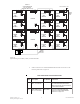
INTRODUCTION The Models FCM-6, LCM-8 and SCM-8 from
Siemens Industry, Inc., are similar in appearance and
identical in installation.
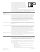
Model FCM-6 Control Module (Figure 1) contains six
sets of three pushbutton switches and their corre-
sponding LEDs. The ON and AUTO switches both
have one bi-color (red/green) LED while the OFF
switch has one bi-color and one yellow LED. The
functions of the switches and LEDs are pro-
grammed using the Zeus Tool (Refer to the Zeus
Quick Start Guide, P/N 315-033875). All LEDs can be
programmed ON, OFF, or FLASHING. The FCM is
designed for general control requiring ON/OFF/AUTO
operation.
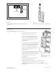
Model LCM-8 LED Control Module (Figure 2)
contains eight pairs of LEDs. Each pair contains one
bi-color (red/green) and one yellow LED. The func-
tions of the LEDs are programmed using the Zeus
Tool (Refer to the Zeus Quick Start Guide, P/N 315-
033875). All LEDs can be programmed ON, OFF, or
FLASHING. These LEDs are used for fire system
status annunciation.
Model SCM-8 Switch Control Module (Figure 3)
contains eight switches and eight pairs of LEDs.
Each pair contains one bi-color (red/green) and one
yellow LED. The functions of the switches and LEDs
are programmed using the Zeus Tool (Refer to the
Zeus Quick Start Guide, P/N 315-033875). All LEDs
can be programmed ON, OFF, or FLASHING. The
SCM is used for manual control of the fire system.
Figure 1
FCM-6 Control Module
Figure 2
LCM-8 LED Control
Module
Figure 3
SCM-8 Switch Control
Module
TRBL
TRBL
TRBL
TRBL
TRBL TRBL
Control Module / LED Control Module / Switch Control Module
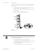
CAN Sounder Board
Installation Instructions
Models FCM-6 / LCM-8 / SCM-8
Model CSB