
Technical data


List of Parameters
Parameters
1-187
© Siemens AG 2011 All Rights Reserved
SINAMICS G120 Control Units CU230P-2 Parameter Manual (LH9), 01/2011
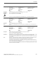
Description: Sets the proportional gain of the I_max voltage controller.
The I_max controller reduces the drive converter output current if the maximum current (r0067) is exceeded.
In the U/f operating modes (p1300) for the I_max control, one controller is used that acts on the output frequency
and one controller that acts on the output voltage. The frequency controller reduces the current by decreasing the
converter output frequency. The frequency is reduced down to a minimum value (equaling twice rated slip). If the
overcurrent condition cannot be successfully resolved using this measure, then the drive converter output voltage is
reduced using the I_max voltage controller. Once the overcurrent condition has been resolved, the drive is acceler-
ated along the ramp set in p1120 (ramp-up time).
Dependency: In the U/f modes (p1300) for textile applications and for external voltage setpoints, only the I_max voltage controller
is used.
Notice: When de-activating the I_max controller, the following must be carefully observed:
When the maximum current (r0067) is exceeded, the output current is no longer reduced, however, overcurrent
alarm messages are generated. The drive is shut down if the overcurrent limit (r0209) is exceeded.
Note: The I_max limiting controller becomes ineffective if the ramp-function generator is de-activated with p1122 = 1.
p1341 = 0: I_max frequency controller de-activated and I_max voltage controller activated over the complete speed
range.
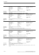
Description: Sets the integral time for the I_max frequency controller.
Dependency: Refer to: p1340
Note: When p1341 = 0, the current limiting controller influencing the frequency is de-activated and only the current limiting
controller influencing the output voltage remains active (p1345, p1346).
In the case of power units with regenerative feedback (PM250, PM260), current limitation control for a regenerative
load is always implemented by influencing the frequency. This current limiting function is de-activated with p1340 =
p1341 = 0.
Description: Displays the effective frequency limit.
Dependency: Refer to: p1340
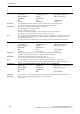
p1340[0...n] I_max frequency controller proportional gain / I_max_ctrl Kp
Access level: 3 Calculated: p0340 = 1,3,4 Data type: FloatingPoint32
Can be changed: U, T Scaling: - Data set: DDS, p0180
Units group: - Unit selection: -
Min Max Factory setting
0.000 0.500 0.000
p1341[0...n] I_max frequency controller integral time / I_max_ctrl Tn
Access level: 3 Calculated: p0340 = 1,3,4 Data type: FloatingPoint32
Can be changed: U, T Scaling: - Data set: DDS, p0180
Units group: - Unit selection: -
Min Max Factory setting
0.000 [s] 50.000 [s] 0.300 [s]
r1343 CO: I_max controller frequency output / I_max_ctrl f_outp
Access level: 3 Calculated: - Data type: FloatingPoint32
Can be changed: - Scaling: p2000 Data set: -
Units group: 3_1 Unit selection: p0505
Min Max Factory setting
- [rpm] - [rpm] - [rpm]