
Operating instructions


Installing
3.3 Installing Power Module
Frequency inverters with Control Units CU230P-2 HVAC, CU230P-2 DP, CU230P-2 CAN
Operating Instructions, 01/2011, FW 4.4, A5E02430659B AD
33
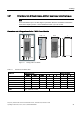
Dimensions and drilling patterns for the PM250 Power Modules
&RROLQJ
DLU
7KHUPDO
GLVVLSDWLRQ
:LGWK
+HLJKW
'HSWK
WRSERWWRP
ODWHUDO ODWHUDO
'HSWK E
D
)6&)6)
)6&)6)
)6&)6)
)6&)6)
F
&RQWURO8QLW
Figure 3-3 PM250 drilling pattern
Table 3- 3 PM250, IP20 dimensions
Dimensions (mm) Clearances (mm) Frame size
Height Width Depth a b c top bottom lateral
FSC 334 189 185 323 167 -- 125 125 50*
FSD without filter 419 275 204 325 235 11 300 300 0
FSD with filter, Class A 512 275 204 419 235 11 300 300 0
FSE without filter 499 275 204 405 235 11 300 300 0
FSE with filter, Class A 635 275 204 541 235 11 300 300 0
FSF without filter 634 350 316 598 300 11 350 350 0
FSF with filter, Class A 934 350 316 899 300 11 350 350 0
Fixing: FSB: M4 screws, 2.5 Nm / 22 lbf .in FSD/FSE:
M6 screws, 6 Nm/53 lbf .in
FSC: M5 screws, 2.5 Nm / 22 lbf .in FSF/: M8
screws, 13 Nm / 115 lbf .in
*) up to 40 °C without any lateral clearance