
Operating instructions


Installing
3.3 Installing Power Module
Frequency inverters with Control Units CU230P-2 HVAC, CU230P-2 DP, CU230P-2 CAN
Operating Instructions, 01/2011, FW 4.4, A5E02430659B AD
41
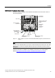
EMC-compliant installation of Power Modules in degree of protection IP20
The EMC-compliant installation of power modules is shown in the following diagram using
two examples.
Example for a connection without a
shield plate via an external filter
Example for a connection with a shield plate, directly
to the line supply
①
Line supply connection
②
Motor connection
③
Metal mounting plate (unpainted and with a good electrical conductivity)
④
Cable clamps for a good conductive electrical connection through a large surface area
between the shield and mounting plate or shield plate.
⑤
Shielded cable for the motor connection
⑥
Shield plate
⑦
Unshielded cable for connection directly to the line supply
⑧
Shielded cable for connection to the line supply via an external filter.
Note
An unshielded cable for the line connection should be used for Power Modules with
integrated filter. Power Modules, which are connected to the line supply via an external filter,
require a shielded cable between the line filter and Power Module.