
Operating instructions


Adapting the terminal strip
5.4 Analog inputs
Frequency inverters with Control Units CU230P-2 HVAC, CU230P-2 DP, CU230P-2 CAN
Operating Instructions, 01/2011, FW 4.4, A5E02430659B AD
89
5.4 Analog inputs
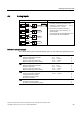
Analog input terminals Changing the function of the analog input
8,
8,
7(03
7(03
,
$,
$,
r0755[0]
CI: pyyyy
p0756[0]
r0755[1]
p0756[1]
$,
$,
$,
*1'
r0755[2]
p0756[2]
r0755[3]
p0756[3]
$,
*1'
1. Define the analog input type using
parameter p0756 and the switch on the
inverter (e.g. voltage input -10 V … 10 V or
current input 4 mA … 20 mA).
2. Interconnect parameter p0755 with a
connector input of your choice (e.g. as
speed setpoint).
Connector inputs are designated with "CI" in
the parameter list of the List Manual.
Define the analog input type
The inverter offers a series of default settings, which you can select using parameter p0756:
AI 0 Unipolar voltage input
Unipolar voltage input monitored:
Unipolar current input
Unipolar current input monitored
Bipolar voltage input (factory setting)
0 V … +10 V
+2 V … +10 V
0 mA … +20 mA
+4 mA … +20 mA
-10 V … +10 V
p0756[0] = 0
1
2
3
4
AI 1 Unipolar voltage input
Unipolar voltage input monitored:
Unipolar current input
Unipolar current input monitored
Bipolar voltage input (factory setting)
0 V … +10 V
+2 V … +10 V
0 mA … +20 mA
+4 mA … +20 mA
-10 V … +10 V
p0756[1] = 0
1
2
3
4
AI 2 Unipolar current input (factory setting)
Unipolar current input monitored
Temperature sensor Ni1000
Temperature sensor PT1000
No sensor connected
0 mA … +20 mA
+4 mA … +20 mA
p0756[2] = 2
3
6
7
8
AI 3 Temperature sensor Ni1000
Temperature sensor PT1000
No sensor connected (factory setting)
p0756[3] = 6
7
8