
Technical data

© Siemens Ⓟ2009
A5E02484096, 05/2009
1
CU230P-2 Control Units
Getting Started
Table of contents
1 Warning and safety information........................................................................................................................................2
2 Documentation for additional support...............................................................................................................................3
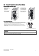
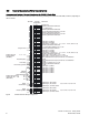
3 Installation .......................................................................................................................................................................3
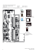
3.1 Interfaces, connectors, control terminals and LEDs on the CU ................................................................................3
3.2 Snap the Control Unit onto the Power Module .........................................................................................................5
3.3 Control terminals of the Control Units.......................................................................................................................6
3.4 Connecting the CU230P-2 HVAC via the RS485 interface ......................................................................................7
3.5 Connecting CU230P-2 DP to the PROFIBUS DP network.......................................................................................8
3.6 Connecting CU230P-2 CAN to CAN bus................................................................................................................10
4 Commissioning ..............................................................................................................................................................12
4.1 Commissioning with STARTER..............................................................................................................................13
4.1.1 Connecting up the inverter for commissioning via STARTER at a PC..............................................................13
4.1.2 Installing USB drivers .......................................................................................................................................14
4.1.3 Creating a STARTER project............................................................................................................................15
4.1.4 Go online with the inverter ................................................................................................................................17
4.1.5 Start commissioning .........................................................................................................................................18
4.1.6 Carrying out commissioning .............................................................................................................................20
4.2 Restoring the factory settings using STARTER......................................................................................................21
4.3 Commissioning with the IOP ..................................................................................................................................22
4.3.1 Commissioning with the IOP.............................................................................................................................23
4.3.2 Commissioning example for inverter operation via terminals............................................................................25
4.4 Restoring the factory settings using the IOP ..........................................................................................................26
4.5 Additional setting options for the inputs and outputs ..............................................................................................26
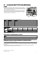
5 Technical data ...............................................................................................................................................................27
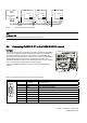
6 Diagnostics....................................................................................................................................................................28
6.1 Operating states indicated on LEDs.......................................................................................................................28
7 Appendix .......................................................................................................................................................................30
7.1 Installing the COM interface ...................................................................................................................................30
7.2 Setting the COM interface ......................................................................................................................................31