Induction Motors/ Generators Horizontal – Medallion 500, 580, 708, 788, 880 Frames TEFC & Explosion-Proof Enclosures Type CZ, NCZ, CGZ, CGZZ ANIM-03522-0402 (New Issue) ©2002 Siemens Energy & Automation, Inc. All rights reserved.
Table of Contents TABLE OF CONTENTS SAFETY PROCEDURES INTRODUCTION Warranty Receiving Handling Temporary Storage Type Designations INSTALLATION Motor Dimensions Location Foundation Mounting Coupling of Sleeve Bearing Motors External Wiring Changing Direction of Rotation Alignment Hot Alignment Vibration Doweling Force Feed Lubrication Typical Motor Control Settings Page 1 2 3 3 3 4 4 4 5 5 5 5 5 5 6 6 6 7 8 8 8 9 OPERATION Initial Start Oil Circulating Systems Normal Operation Voltage/Frequency Variation
Safety Procedures Do not operate this equipment in excess of the values given on nameplate or contrary to the instructions contained in this manual. The equipment (or a prototype) has been factory tested and found satisfactory for the condition for which it was sold. Operating in excess of these conditions can cause stresses and strains beyond design limitations. Failure to heed this warning may result in equipment damage and possible personal injury. This equipment contains hazardous voltages.
Introduction temporary film of rust inhibiting oil or, when a motor is supplied specifically with “provisions for oil mist lubrication” (oil supply system furnished by the user), the motor is shipped from the factory with grease in the bearings. DANGER Hazardous voltage. Will cause death, serious injury, electrocution or property damage. Disconnect all power before working on this equipment. When receiving a motor with sleeve bearings: 1. Remove shaft blocking materials. 2.
Introduction Temporary Storage WARNING Heavy equipment. Improper handling may cause death, serious injury or property damage. Check lifting devices before lifting. Use proper slings, chains and spreaders. Note any warning plates on motor and follow instructions on each plate. Handling Lifting devices are provided for handling only. An experienced rigger should be used to install motors. To avoid damage, the use of spreader bars is recommended on other than single point lifts.
Installation Motor Dimensions For motors built in the frame sizes covered by this manual, the letter dimensions have the same definitions as established NEMA standards. Established dimensions for these frames may be found on catalog sheets or certified drawings. CAUTION Before pouring, locate foundation bolts by use of template frame and provide secure anchorage (not rigid). It is recommended that a fabricated steel base be used between motor feet and foundation.
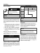
Installation External Wiring Motor Fan Direction Motor Speed Frame DANGER 3600 – 3000 RPM 1800 – 1500 RPM 1200 RPM & SLOWER 500 Hazardous voltage. Will cause death, serious injury, electrocution or property damage. Disconnect all power before working on this equipment. 580 NON-DIRECTIONAL 708 788 NOTE DIRECTIONAL 880 Before running motor, see Initial Start. Starting and overload control devices must be matched to motor rating.
Installation Angular Alignment Hold each shaft at maximum end float. Rotate both shafts together, and measure between matching points at the outside diameter of the coupling faces for the top, bottom and both sides. Use two indicators because of possible axial shaft movement. Read difference of variation between them. 3. If no change is indicated, retighten the bolt and repeat the process for each of the remaining three mounting bolts. 4.
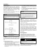
Installation Check for vertical alignment (parallelism) of coupled drive as follows: 1. Operate unit until normal temperature is reached (may require several hours). 2. Shut down motor and lock out switch. 3. Mount dial indicator as in Figure 2. 4. Rotate shaft, noting readings at 0°, 90°, 180°, and 270° (both sides, top, and bottom). If within 0.002 inch total indicator reading, or other limit specified by the factory, unit is satisfactory for operation. 5.
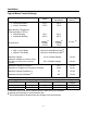
Installation Typical Motor Control Settings Alarm Trip (Shutdown) Winding Temperature • Class B Insulation • Class F Insulation 130°C 155°C 155°C 170°C Motor Bearing Temperature (Thermocouple or RTD’s) • Sleeve Bearing • Antifriction Bearing 90°C 100°C 95°C 105°C 4 Amps (2) Primary Circuit 8 Amps (2) Primary Circuit Ground Fault Timer Trip Setting (1) 0.2 sec. (2) Instantaneous Overcurrent • • With ½ Cycle Delay Without Time Delay 1.8 times Locked Rotor Amps (2) 2.
Operation Initial Start Oil Circulating Systems For motors with oil circulating systems, proceed as follows before startup; CAUTION Do not exceed number of Siemens specified hot and cold starts per hour. Will cause overheating. Allow time between starts to permit stator windings and rotor cage to cool. 1. Fill motor reservoirs to normal level (see motor outline drawing). 2. Follow instructions provided by the oil circulating system supplier. 3.
Operation Trouble Shooting DANGER Hazardous voltage. Will cause death, serious injury, electrocution or property damage. Disconnect all power before working on this equipment. Between regular maintenance inspections, be alert for signs of motor trouble. Common symptoms are listed in the following table. Correct any trouble immediately and AVOID COSTLY REPAIR AND SHUT DOWN. TROUBLE Motor will not start. POSSIBLE CAUSES CORRECTION Usually line trouble. Single phasing at starter. Check power source.
Operation Trouble Shooting DANGER Hazardous voltage. Will cause death, serious injury, electrocution or property damage. Disconnect all power before working on this equipment. TROUBLE Motor overheating (continued…) POSSIBLE CAUSES CORRECTION Open stator windings. Disconnect motor from load. Check idle amps for balance in all three phases. Check stator resistance in all three phases for balance. Air Recirculation. Check air intake and exhaust for obstructions. Check air inlet temperature.
Maintenance Preventive Maintenance Motors are designed to give many years of reliable service with a minimum of attention. Trouble-free operation cannot be expected if proper maintenance is postponed or neglected. Provide proper maintenance on the equipment. Follow carefully the instructions contained herein. Be certain personnel review, understand, and follow these procedures during periodic maintenance inspections. DANGER Hazardous voltage.
Maintenance WARNING Explosion or fire. Can cause death, serious injury or property damage. Do not modify explosion-proof or dust ignition-proof motors. These motors are constructed to comply with the U.L. Label Service Procedure Manual. When reassembling a motor that has a U.L. Label, it is imperative that: 1. The original fits and tolerances be maintained. 2. All plugs and hardware be securely fastened. 3. Any part replacements are accurate duplicates of the original. 4.
Maintenance Temperature Electrical apparatus operating under normal conditions becomes quite warm. Although some places may feel hot to the touch, the unit may be within limits. If checking total temperature by winding resistance or imbedded detector (RTD), the total temperature should not exceed the following: When operating at full load: Class of Insulation System Temp. by Resistance Temp.
Maintenance Rotor Cleaning Remove rotor. Inspect and clean. Stator Cleaning MICLAD™ form wound VPI (vacuum pressure impregnated) insulated coils may be cleaned with a quick drying solvent and lint free cloths or steam cleaned with low-pressure steam, then the entire stator oven baked at 200°F for 12 hours and then 230°F for 12 hours. The stator winding insulation resistance should be measured before and after any cleaning operation.
Maintenance Electric Strip Heater Drying 1. Remove bearing housings. 2. Remove rotor. 3. Direct a fan on stator to carry away the moisture. 4. Attach temperature indicators to winding and apply heat as specified in the Insulation Drying Temperature table and follow procedures described for drying insulation. 5. Radiant type heaters are not recommended because some parts may become scorched before remote parts reach desired temperature. Circulating Current Drying 1. Remove bearing housings. 2.
Maintenance Insulated Bearings One or both bearings may be insulated to prevent shaft currents from pitting bearing surfaces. The insulation is located at the joint between the bearing housing or bracket and the bearing. Insulated bearings are designated by an instruction plate on the bearing housing. Check periodically to be sure the insulation has not been weakened or destroyed. The bearing insulation can be checked using an ohmmeter or circuit test light.
Maintenance At the first sign of oil discoloration or contamination, replace with new oil. Rapid discoloration is caused by bearing wear, often from vibration or thrust. Change oil as required to keep clean. When assembling the bearing, it is possible to foul the rings so that they will not turn freely. Check ring operation by rotating shaft by hand after assembly Oil Seals 580 frame motors use fixed, labyrinth oil seals to close off the bearing cavity.
Maintenance Sealing Parts Even though joints may seem to match perfectly, minute clearances exist through which oil may leak. Sealant should be applied to the mating surfaces of parts where oil is present to prevent seepage of oil. The frequency of lubricating bearings depends on three factors - speed, type of bearing, and service. Sealant should be applied as follows: Lubricate with the type of grease specified on the lubrication plate mounted on the motor, or a compatible grease.
Maintenance 1. 2. 3. Sleeve Bearings CAUTION 4. Maintain proper oil level. Failure to do so may cause improper lubrication of motor resulting in damage to the equipment. Follow lubrication instructions carefully. Avoid adding oil while unit is running. Motors with sleeve bearings are shipped without oil. A rust-inhibiting film is applied at the factory to protect bearing and journal surfaces during shipment. Before attempting to operate any sleeve bearing motor, the following steps must be performed.
Maintenance To Replace Antifriction Bearings 1. 2. 3. 4. 5. Remove bolts holding end caps to housings. Remove bolts holding bearing housings to yoke. Remove bearing housings. Remove the bearing with a puller. See Figure 5. Check shaft and housing diameter for proper size with micrometer. 6. Heat the new bearing in an oven (200°F). While it is hot, slide the bearing onto shaft – make certain that the inner race makes a firm even contact with shaft shoulder. Do not subject bearing to impact. 7.
Maintenance Sleeve Bearing When replacing sleeve bearings, it is always desirable to check the fit (contact pattern) of the bearing to the shaft. When ordering sleeve bearings, be sure to provide complete motor nameplate and bearing data. Whenever a bearing is replaced, cleanliness must be observed through every step of the operation. Always inspect the bearing journal surfaces; they must be smooth and polished. Slight scoring can be removed with crocus cloth.
708, 788, and 880 Frames (See Figure 8) 1. Check replacement bearings for nicks or shipping damage. Do not scrape. 2. Carefully remove the bearing housing cap by first lifting straight up, then pulling away from the bearing area. 3. Remove top half of bearing liner. 4. Remove the bolts at the split line of the oil ring. 5. Remove bearing temperature probes if so equipped. 6. Raise the shaft slightly and support it. 7. Rotate the lower bearing half 180° and remove the lower half of the bearing. 8.
Identification All units have an identification nameplate affixed to the frame (Figure 9). All the necessary information pertaining to the motor can be found on this plate including; 1. Serial Number 2. Type and Frame Size 3. Horsepower and Speed 4. Bearing Designations It is important when ordering spare parts or discussing service to have as much data from this plate as possible. Parts Identification Figures 10 through 18, are of a standard design. Your motor may differ slightly.
Figure 10. Type CZ, 509 & 5011 Frames Item 1 2 3 4 5 6 Description Stator Core Stator Yoke Stator Coils Bearing Housing Rotor Shaft Inner End Cap Item 7 8 10 11 12 13 Description Ball Bearing Shaft Seal Grid Cover Rotor Core External Fan (4 pole & slower) Fan Housing Item 14 15 16 17 18 19 Description Inboard Seal Oil Seal Bearing Capsule Sleeve Bearing Bushing Shims (in bottom half) Oil Rings Item 1 2 3 4 5 6 7 8 9 10 11 12 13 Figure 11. Type CGZZ, 507, 509, and 5011 Frames. (U.L.
Spare Parts Item 16 17 18 19 20 21 22 23 24 Description Fan Cone External Fan (2pole) Inside Oil Seal Bearing Cap. Housing Sleeve Bearing Bushing Shims Outside Oil Seal Oil Rings Machine Seal Figure 12. External Fan Arrangement for 2 Pole Types CZ, CGZ, & CGZZ. Item 1 2 3 4 5 6 7 Figure 13.
Spare Parts Item 1 2 3 4 5 6 7 Description Stator Core Stator Yoke Stator Coils Bearing Housing Rotor Shaft Inner End Cap Ball Bearing Item 8 10 11 12 13 14 15 Description Shaft seal Grid Cover Rotor Core External Fan (Non-Directional) Fan Housing Internal Fan Rotor Air Duct Figure 15. Sleeve Bearing Arrangement for Type CGZ 708, 788, & 880 Frames Item 18 19 20 21 22 23 Description Oil Seal Bearing Cap. Housing Sleeve Bearing Bushing Shims Machine Seal Oil Ring Figure. 16.
Motor Service Record ______________________ Horsepower ______________ Type ___________ Serial No _____________ Amperes _____________ Hertz _______ Speed ________ Volts Insulation Class _______ Owner Order No _________________ MACHINE TYPE Horizontal Vertical (1) Name of Part Item No _______ _____ °C BEARINGS Ball Roller Sleeve Length ___________________ Diameter _________________ Internal Thread ____________ External Thread ____________ Keyway __________________ Application R
Vibration Analysis Sheet Pick-Up Point Position Horizontal Vertical Axial Horizontal Vertical Axial Horizontal Vertical Axial Horizontal Vertical Axial Horizontal Vertical Axial Horizontal Vertical Axial Horizontal Vertical Axial Horizontal Vertical Axial Horizontal Vertical Axial Horizontal Vertical Axial Horizontal Vertical Axial Disp. Mils Filter-Out Coupled Freq* Vel. Freq.* CPM In/Sec CPM Vel. Mils Freq. CPM Vel. Mils Filter-In Coupled Freq. Vel. Freq. CPM Mils CPM Vel. Mils Freq.
Notes __________________________________________________________________________________________ __________________________________________________________________________________________ __________________________________________________________________________________________ __________________________________________________________________________________________ __________________________________________________________________________________________ __________________________________________________
Notes __________________________________________________________________________________________ __________________________________________________________________________________________ __________________________________________________________________________________________ __________________________________________________________________________________________ __________________________________________________________________________________________ __________________________________________________
Siemens Energy & Automation Industrial Products Division Norwood Motor Plant 4620 Forest Avenue Norwood, OH 45212-3396 (513) 841-3100 ANIM-03522-0402 (New Issue) ©2002 Siemens Energy & Automation, Inc. All rights reserved.