
Data Sheet for Product

Siemens
Smart Infrastructure - Building Products
–3–
usa.siemens.com/fire
Installation
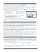
All Model FDOT421 detectors use a surface-mounting base | Model DB2-HR | DB-11 or Model DB-11E. Each base
mounts onto a 4-inch (10.2 cm.) octagonal, square or single-gang electrical box. The base utilizes screw-clamp
contacts for electrical connections and self-wiping contacts for increased reliability.
The Model DB-11 detector base can be used with the optional Siemens Model LK-11 detector locking kit, which
contains 50 detector locks and an installation tool to prevent unauthorized removal of the detector head. Model DB-11
has aesthetically conducive plugs to cover the outer mounting-screw holes.
Model FDOT421 may be installed on the same initiating circuit with the following [when used with Desigo Fire Safety
Modular Model FC20-series | FireFinder XLS/V FACPs] –
Each detector is shipped with a protective dust cover, consists of the following:
•
Built-in ISOtechnology for True-Class-X SLC performance
• Dust-resistant photoelectric chamber
• Solid State, non-mechanical thermal sensor
• Microprocessor-based electronics with a low-profile plastic housing
All Model FDOT42
1 detectors are approved for operation within the UL-specified temperature range of 32°F to 100°F
(0 – 38°C).
Application Data
Installation of Model FDOT421 intelligent, addressable multi-criteria detectors requires a two-wire circuit.
In many retrofit cases, existing wiring may be used. `T-tapping’ is permitted only for Style 4 (Class B) wiring.
Model FDOT421 is polarity insensitive, which can greatly reduce installation and debugging times. When operating in
NFPA 72 Class-X applications SLC polarity must be maintained to support up to 252 isolation ready devices per loop.
When used in mixed mode a maximum of 30 non-isolated devices between isolation devices (wired in polarity-
insensitive mode). See control panel install document for further details.
Model FDOT421 can be applied within the maximum 50-feet (15.24 m.) center spacing (2,500 sq. ft.
[232.2 sq. m.]) per Underwriters’ Laboratories. This application guide is based on ideal conditions, specifically,
smooth-ceiling surfaces, minimal air movement, and no physical obstructions between potential fire sources and the
actual detector. Do not mount detectors near to heating | ventilation | air-conditioning (HVAC) outlets. Exposed joists
or beamed ceilings may also affect safe spacing limitations for detectors.
Should questions arise regarding detector placement, observe NFPA 72 guidelines. Good fire-protection system
engineering and common sense dictate how and when fire detectors are installed and used. Contact your local
Siemens
– Fire Safety distributor or sales office whenever you need assistance applying Model FDOT421 in unusual
applications.
Be sure to follow NFPA guidelines and UL Listed / ULC Listed installation instructions
– included with every Siemens –
Fire Safety detector
– and local codes for all fire-protection equipment.
Specifications
Model FDOT421 is a plug-in, (2) two-wire Photoelectric | Thermal (heat) detector, compatible with Model FC20-series
Desigo Fire Safety Modular Model FC20-series | FireFinder XLS/V FACPs. Each Model FDOT421 detector has
microcomputer-chip technology and highly stable, solid-state electronic circuitry. Model FDOT421 detectors utilize a
modern, accurate and shock-resistant thermistor to sense temperature changes. This electronic-sensing method
virtually eliminates thermal lag associated with mechanical temperature-sensing devices, and provides almost
instantaneous temperature status to the FACP.
Model FDOT421 provides seven (7) field-selectable, pre-programmed temperature settings:
• Fixed 135°F (57°C)
• Rate-of-Rise: 15°F / min. (8.3°C)
This feature is compatible with Model FC20-series Desigo Fire Safety Modular Model FC20-series | FireFinder XLS/V
systems, as well as with FC / FV2025 or FC / FV2050 FACPs.
• XTRI Series interface modules
• HFP-11, HFPT-11 detection devices
• HTRI series interface modules
• HCP output control modules
• HMS & XMS series manual stations
• HZM conventional zone module
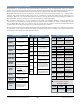
Dimensional Data