
Data Sheet for Product

s Canada Limited Cerberus® PRO
Installation
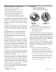
All Model OOH941 detectors use a surface-mounting
base (Model DB-11 or Model DB-11E), which mounts
on a 4-inch octagonal, square or single-gang electrical
box. The base utilizes screw-clamp contacts for
electrical connections and self-wiping contacts for
increased reliability.
The Model DB-11 base can be used with the optional Model
LK-11 detector locking kit, which contains 50 detector locks
and an installation tool to prevent unauthorized removal of
the detector head. Model DB-11 has decorative plugs to
cover the outer mounting screw holes.
Model OOH941 may be installed on the same initiating
circuit with the Siemens Model `H’-series detectors
[when used with Cerberus PRO FACPs]
─
• Models HFP-11, HFPT-11
• Model ‘HMS’-series manual stations
• Model ‘HTR
I’-series interfaces
• Model HCP output-control devices
• Model ‘HZM’-series of addressable,
conventional zone modules
Each detector consists of the following:
Dust-resistant photoelectric chamber
Solid state, non-mechanical thermal sensor
Microprocessor-based electronics with
a low-profile plastic housing
Each Model OOH941 fire detector
is shipped with a protective dust cover:
All Model OOH941 detectors are approved for
operation within the
UL-specified temperature
range of 32° to 120°F (0° to 49°C)
─ depending on
heat-detector configuration
(See to installation:
P/N – A6V10324655 for details).
Application Data
Installation of Model OOH941 detectors requires a two-
wire circuit.
In many retrofit cases, existing wiring may
be used. ’T-tapping’ is permitted only for Style 4 (Class
B) wiring. Model OOH941 is polarity insensitive, which
can greatly reduce installation and debugging time.
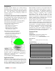
Model OOH941 fire detectors can be applied within the
maximum 30-feet center spacing (900 sq. ft. areas,) as
referenced in NFPA 72. This application guideline is
based on ideal conditions
─ specifically, smooth ceiling
surfaces; minimal air movement, and no physical
obstructions between potential fire sources and the
actual detector. Do not mount detectors in close
proximity to ventilation or heating and air conditioning
outlets. Exposed joints or beamed ceilings may also
affect safe spacing limitations for detectors.
Should questions arise regarding detector placement,
observe NFPA 72 guidelines. Good fire-protection-
system engineering and common sense dictate how and
when fire detectors are installed and used. Contact your
local Siemens
─ Fire Safety distributor or sales office
whenever you need assistance applying Model OOH941
in unusual applications. Be sure to follow NFPA
guidelines and
ULC Listed installation instructions ─
included with every Siemens − Fire Safety detector
─ and
local codes as for all fire protection equipment.
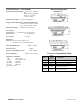
Technical Data
Operating
Temperatures:
+32°F (0°C) to 120°F (49°C)
depending upon heat-detector configurations
(see to installation manual: P/N A6V10324655) for details
Heat-Detector
Range:
+135°F (57°C) to 175°F (79°C)
Thermal Ratings:
OOH941 Field-Selectable Temperature Profiles
Fixed Temperature, 135°F
Fixed Temperature, 145°F
Fixed Temperature, 155°F
Fixed Temperature, 165°F
Fixed Temperature, 175°F
Fixed Temperature, 135°F + Rate-of-Rise (R-o-R) 15°F
Fixed Temperature, 175°F + Rate-of-Rise (R-o-R) 15°F
Fixed Temperature, 135°F + Rate-of-Rise (R-o-R) 20°F
Fixed Temperature, 175°F + Rate-of-Rise (R-o-R) 20°F
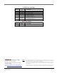
Field-Selectable, Alarm-Threshold Setting Profiles
2.5 % / ft. threshold
3.0 % / ft. threshold
2.5 % / ft. threshold (verified)
3.0 % / ft. threshold (verified)