
Data Sheet for Product
s Industry, Inc.
Building Technologies Division
Specifications ─ (continued)
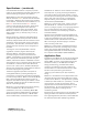
Under normal conditions, light transmitted by the LED
is directed away from the photodiode and scattered
through the smoke chamber in a controlled pattern.
The smoke chamber is designed to manage light
dissipation and extraneous reflections from dust
particles or other non-smoke airborne contaminants in
such a way as to maintain stable, consistent detector
operation. When smoke enters the detector chamber,
light emitted from the
IRLED is scattered by the smoke
particles, and is received by the photodiode.
Model FP-11 also utilizes a modern, accurate and
shock-resistant thermistor to sense temperature
changes. The ‘on-board’ FirePrint technology
allows the detector to gather smoke and thermal
data, analyzing this data in the detector’s ‘neural
network.’ By comparing data received with the
common characteristics of fires, or fire fingerprints,
Model FP-11 can compare these ‘fire prints’ to those
of deceptive phenomena that cause other detectors
to go into Alarm mode.
This advanced FirePrint technology allows Model
FP-11 to accurately determine a true fire hazard from
non-threatening, deceptive phenomena
─ without the
need to use alarm-delaying verification and
confirmation techniques; thus decreasing the
probability of losses in infrastructure from an actual fire.
Model FP-11 provides the highest level of detector
intelligence available today with a detector / control-
panel link that allows the user to program the
detector for the specific hazard profile.
Detectors are optimized by selecting one (1) of
the following applications:
• Office / Retail
• Lobby
• Computer room
• Dormitory
• Healthcare facility
• Parking garage
• Utility / transformer room
• Hostile environment
• Precious storage
• Air duct
• Warehouse / light manufacturing
Once programmed, the software does the rest −
no guessing on detector sensitivities or alarm
verification − the FACP programs Model FP-11 for the
protected area without any confirmation delays.
Once optimized for the hazards in the protected area,
Model FP-11 provides the utmost means in detection.
Should the operator or installer forget
to program the detector, Model FP-11 will revert
to a default setting that, in turn, allows operation
as a standard photoelectric or photothermal detector.
The FirePrint technology for Model FP-11 monitors
input from the photo chamber and the thermal
sensor, evaluating this information with sophisticated
mathematical formulas or algorithms, and compares
data transfer to this input to the characteristics of
both threatening fires and deceptive phenomena that
would deceive any ordinary detector.
This technology was developed over years of research
and reviewing the results of over 20 years of fire-test
data in one of the world’s most advanced fire research
centers. The results of this research are the
mathematical models that form the algorithms used
in FirePrint. No other fire detector has this level of
intelligence or this amount of research and
development supporting its design.
The software of the microprocessor can identify and
disregard false input caused by radio frequency (RF
I)
and electromagnetic (EMI) interference, and validates
all Trouble conditions before annunciating or
reporting to the control panel. The microprocessor
for Model FP-11 uses an integral electronically
erasable programmable read-only memory (EEPROM)
to store the detector’s address and other critical
operating parameters, which include the assigned
program values for Alarm and Trouble–command
thresholds.
Communications within the detector; between Model
FP-11 and the FACP, or with the field programmer /
tester (Model DPU / FP
I-32), are supervised and
safeguarded against disruption by reliable,
microprocessor-based error checking routines.
Additionally, the microprocessor supervises all
EEPROM memory locations and provides a high
degree of EEPROM failure fault tolerance.
Model FP-11 determines its operating status (Normal,
Alarm, or Trouble modes) based upon the difference
between the alarm-threshold values stored in the
detector’s memory and the detector’s latest analog
measurement. The detector then communicates
changes in its status to the FACP.
In addition, the FACP will sample the value of the
analog signal for Model FP-11 over a period of time, in
order to determine if those values indicate excessive
buildup in the photo chamber.
In the event of
excessive buildup, the FACP will accurately indicate
which detector shall require maintenance.
Model FP-11 is listed as a self-testing device. The LED
for Model FP-11 flashes green every four (4) seconds,
indicating communication with the FACP, and that it
has passed its self-test. Should the detector sense a
fault or failure within its systems, the LED will flash
amber, and the detector will transmit that data to the
FACP. A quick visual inspection is sufficient to
indicate the condition of the detector at any time.