
Installation Instructions

Installation Instructions
Base Models DB-3S/X3RS
This installation guideline is written in accordance with the installation
guidelines of NFPA 72, National Fire Alarm Code and CAN/ULC-S524,
The Installation Of Fire Alarm Systems.
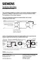
INSTALLATION/WIRING DIAGRAM FOR SIEMENS MODEL DB-3S USING
CONVENTIONAL DETECTORS
INSTALLATION/WIRING DIAGRAM FOR
SIEMENS
MODELS DB-3S AND DB-X3RS
USING IL SERIES DETECTORS OR FP SERIES DETECTORS
Figure 1
Installation/Wiring Diagram
5
5
6
6
1a
+
+
_
_
1a
1b
1b
End of line
device
Zone wires from Siemens Industry, Inc.
initiating device circuit. See detector
installation instructions for compatible
systems and modules.
If supported by detector
and zone, connect to RL-30,
RL-40, RLI-1, or RLI-2 remote
lamps or remote relay RR-3.
CAUTION: Do not use looped wire under terminal 5. Break wire run to provide supervision of connection.
_
_
__
_
_
_
+
+
+
+
++
+
61a
55
5+
5+
6-
6-
NO
C
NC
NO
C
NC
66
1b 1b
1a 1a
Optional
Remote
Alarm
Indicator
Models
RLI-1, RLI-2
Detector Base
Model DB-3S
Remote Relay
Base Model DB-X3RS
To Next Base
Relay*
Contacts
3A, 120 VAC
3A, 30 VDC
The relay contacts are shown after a system reset pulse, which represents the non-alarm condition.
The contact state may vary prior to system initialization.
*
To Next Base
Do Not
Use an
End of
Line
Device
Zone wires from
Siemens Industry,
Inc. initiating
device circuit. See
detector
installation
instructions for
compatible
systems and
modules.
P/N 315-083225-15
Siemens Industry, Inc.
Building Technologies Division
Florham Park, NJ
Siemens Building Technologies, Ltd.
Fire Safety & Security Products
2 Kenview Boulevard
Brampton, Ontario
L6T 5E4 Canada