
Installation Instructions

DETECTOR PLACEMENT
Although no specific spacings are allocated to these detectors, maximum 30
foot center spacing (900 sq ft) from NFPA Standard 72 Chapter 5 and
CAN/ULC-S524 may be used,
if practical, as a guide or starting point in a
detector installation layout. This spacing, however, is based on ideal condi-
tions - smooth ceiling, no air movement, and no physical obstructions.
In all installations (except in special circumstances, such as in computer
room underfloors), locate the detector on the ceiling, a minimum of 12 inches
from a sidewall, or on a wall, between 4 and 6 inches from the ceiling.
Should questions arise regarding detector placement, follow the drawings
provided or approved by Siemens Industry, Inc. or by its authorized distribu-
tors. This is extremely important! The detector placements shown on these
drawings were chosen after a careful evaluation of all facets of the area
protected.
Environmental factors such as air currents, temperature, humidity, pressure,
and the nature of the fire load are carefully considered. Special consideration
is given to room or area configuration and the type ceiling (sloped or flat,
smooth or beamed). Siemens Industry, Inc.'s extensive experience in the
design of the system assures the optimum detector placement and is re-
flected in these drawings. The sound engineering judgment of qualified
personnel must be followed.
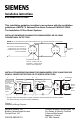
DETECTOR WIRING
Siemens Industry, Inc.'s detectors should be interconnected as shown in
Figure 1 and wired to the control panel following the wiring connection draw-
ing installed on the inside face of each control panel cover. Duplicate wiring
information is also in the Installation, Operation, and Maintenance Manual
provided with every control panel. Note any limitations on the number of
detectors permitted on each circuit.
DETECTOR MOUNTING - USING THE DB-3S
The detector is provided with a separate base which attaches to a standard 4
inch square, 4 inch octagonal, or single gang electrical box, with the box size and
depth required by the NEC for the number and size of conductors used.
MOUNTING - USING THE DB-3S
1. Route all wires outward from outlet box.
2. When the ALARM LED viewing is critical, position the LED mark in the
base in the intended direction. Refer to Figure 2.
Figure 2
Mounting the Base