
Installation Instructions
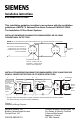

3. Mount base to outlet box and route wires through the hole in the center of
the base. Make connections directly to the base terminals. Refer to Figure
1 for details.
4. After all bases are installed, including the end-of-line device, check loop
continuity. Refer to the System Manual for the loop continuity check
procedure. To make possible the continuity check, a jumper is furnished
in every base (between terminals 1a and 1b) to complete the loop.
(Refer to Figure 2.) An open circuit condition exists until the jumper or
detector is installed in the base.
5. If loop continuity is acceptable, remove the jumper at each base and
proceed with detector head installation.
6. To insure proper installation of the detector head into the base:
a. Properly dress all wires.
b. Position all wires flat against the base.
c. Take up all slack in the outlet box.
d. Route wires away from connector terminals.
DETECTOR MOUNTING - USING THE DB-X3RS
The detector is provided with a separate base which attaches to a standard 4
inch square, 2
1
/
8
inch deep electrical box, with the box size and depth required
by the NEC for the number and size of conductors used.
MOUNTING - USING THE DB-X3RS
1. Route all wires outward from outlet box.
2. When the ALARM LED viewing is critical, position the LED mark in the
base in the intended direction. Refer to Figure 2.
3. Remove the jumper installed between terminals 1a and 1b.
4. Mount the base to the outlet box and route the wires through the hole in
the center of the base. Make connections directly to the base terminals.
Refer to Figure 1 for details.
5. To insure proper installation of the detector head into the base:
a. Properly dress all wires.
b. Position all wires flat against the base.
c. Take up all slack in the outlet box.
d. Route wires away from connector terminals.
CAUTION
Detector Storage
DO NOT install this detector until all
construction is completed.
DO NOT store this detector where it can
be contaminated by dirt, dust, or humidity.