
Installation Instructions
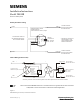
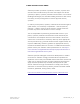


Class X Wiring (Isolator mode):
OPTIONAL
REMOTE
ALARM
INDICATOR
MODELS
8727W / 8727C /
RL-HW / RL-HC
TO NEXT BASE
TO NEXT BASE
DO NOT USE AN
END OF LINE DEVICE
DETECTOR BASE
MODEL DB-11/DB-11E
LINE 1
LINE 2
5
6
1a
TB1
TB3
TB2
1b
5
6
1a
1b
* The relay contacts are shown after System reset, which represents the non-alarm condition.
5+
NO
C
NC
6-
RELAY *CONTACTS
3A, 120 VAC
3A, 30 VDC
DO NOT USE AN
END OF LINE DEVICE
++
– –
To initiating circuit of
SIEMENS compatible control unit
Wires connected to TB3/TB4 must enter or exit electrical box on opposite side of wires connected
to TB1, if TB1 is used in an AC Power or Non-Power Limited application.
Figure 1
DB2-HR Wiring for Polarity Insensitive Detectors
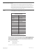
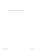
*THE RELAY CONTACT
S
ARE SHOWN IN THE
NON-ALARM/SYSTEM
RESET CONDITION.
DO NOT USE AN END
OF LINE DEVICE
T
O
NEXT DEVI
CE
DO NOT USE AN END
OF LINE DEVICE
TO NEXT DEVICE
5
NC
NO
COM
6
TO INITIATING CIRCUIT
OF SIEMENS INDUSTRY,
INC. CONTROL PANEL
REMOTE RELAY BASE
MODEL DB2-HR
INPUT RATING: 24VDC, 200 Aµ
LINE 2
LINE 1
LINE 2
LINE 1
RELAY*
CONTACTS
3A, 120 VAC
3A, 30 VDC
6
5
1b
1b
T
B
4
T
B
3
T
B
1
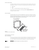
Detector Relay Base
Installation Instructions
Model DB2-HR
Siemens Siemens
Siemens Siemens
Siemens
IndustryIndustry
IndustryIndustry
Industry
,,
,,
,
Inc. Inc.
Inc. Inc.
Inc.
SmarSmar
SmarSmar
Smar
t Infrastructt Infrastruct
t Infrastructt Infrastruct
t Infrastruct
ureure
ureure
ure
A6V10327325_en--_b
Polarity Insensitive wiring: