
User guide


7
en
Technical data
DE 1821555 DE 2427555
Rated output
[kW]
18
21
24
27
Rated voltage
[V] 400 400
Fuse protection
[A] 32 40
Minimum conductor cross-section
[mm
2
]4 6
Warm water flow at rated output
with temperature increase from
12 °C to 38 °C [l/min]
9.9
11.6
13.2
13.9
12 °C to 60 °C [l/min]
5.4
6.3
7.2
7.6
Start-up flow
[l/min] 2.6 2.6
Start-up flow pressure *
[MPa (bar)] 0.025 (0.25) 0.025 (0.25)
Application area in water
specific electric resistance at 15 °C
[Ωcm] ≥ 1 300 ≥ 1 300
Rated pressure
[MPa (bar)] 1.0 (10.0) 1.0 (10.0)
Maximum permissible supply temperature
[°C] 55 55
Maximum mains impedance at connection
point
[Ω] ≤ 0.244 ≤ 0.244
* The pressure loss on the mixer must also be added
Operation with prewarmed water (solar heated)
The continuous-flow heater can only heat prewarmed water
to a max. of 60 °C. If the cold water supply exceeds a tem-
perature of 55 °C, the water will not be warmed any further.
Important: The cold water supply temperature must not be
higher than 55 °C!
If the cold water supply exceeds a temperature of 60 °C, a
circuit breaker will trigger and shut the appliance off. There-
fore, the residential plumbing must be equipped with a ther-
mostatic premixer (e. g. special accessory BZ 45T20) that will
limit the cold water supply temperature to a max. of 55 °C by
appropriately mixing in cold water.
VI.
Startup/additional information
First start-up
Switch on the fuses.
■
Setting the temperature. ■
Starts rinsing: Open the warm water tap and allow water ■
to flow for at least 1 minute (flow-rate at least 6 litres per
minute). Only then (for safety reasons) will the appliance
begin to heat.
Tip: Should the appliance not start because of a reduced
flow-rate, remove the perlator, shower head or similar before
start and repeat the process.
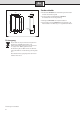
Remove the flow-rate limiter (see Fig. A) with low water
■
pressure.
Explain the operation of the continuous-flow heater to
■
the user.
A
If the continuous-flow heater does not have sufficient
water flow due to low water line pressure in your do-
mestic plumbing system, remove the flow-rate
limiter.
B
Priority circuit for the combination with electrical
storage heaters:
For operation with a priority circuit, a special load
shedding relay BZ 45L20 (special accessory) is re-
quired. Other existing load shedding relays, with the
exception of electronic load shedding relays, may
malfunction.
C
The control electronics must be coded when operated
with a load shedding relay.
D
The filter upstream from the check valve in the cold
water supply inlet is clogged.
Remove the filter and either clean it or descale it.
See Figure D 1–3.