LMSmod Configuration Guide V2.1 Document no Edition Supersedes Manual Section e1109a 9.
TABLE OF CONTENTS TABLE OF CONTENTS 1. INTRODUCTION____________________________________________________________7 1.1 The aim of this manual ___________________________________________________________________ 7 1.2 Who this manual is for ___________________________________________________________________ 7 1.3 How this manual is organized _____________________________________________________________ 7 1.4 The configuration process ________________________________________________________________ 8 2.
TABLE OF CONTENTS 4.4.4 Time programs ______________________________________________________________________ 64 4.4.5 Warnings ___________________________________________________________________________ 66 4.4.6 The typical week _____________________________________________________________________ 70 4.4.7 Holidays____________________________________________________________________________ 71 4.4.8 Daylight Saving time __________________________________________________________________ 72 4.4.
TABLE OF CONTENTS 7.7 Export pages _________________________________________________________________________ 110 8. PAK MANAGER __________________________________________________________113 8.1 What is PAK ? ________________________________________________________________________ 8.1.1 Base software modules ______________________________________________________________ 8.1.2 Optional software modules ____________________________________________________________ 8.1.
INTRODUCTION 1. INTRODUCTION 1.1 The aim of this manual This manual provides all of the information and instruction necessary to build a database for the Local Monitoring System (LMS) and to configure its various functions.
INTRODUCTION find here a description of the INSTALLATION configuration in Par. 4.2. Then Par. 4.3, INTERNAL DATA, describes the Description and Treatment table configuration. In Chapter 4 are also explained SEQUENCES, which are short programs that can test and manipulate the security devices. The chapter deals with the time-driven functions, and namely with holidays, typical week, time programs, warnings and daylight saving time configuration.
INTRODUCTION Fire detection system CS11 subsystems Intrusion detection system CS4 subsystems site First, the Database Configurator is used to define the physical locations, or Sites. Sites usually represent buildings; each building is a separate site. Speaking more generally, a site is a geographical entity. It is a group of systems in one place. An office building, a warehouse, or a store could be a site.
INTRODUCTION After the Sites, Systems, Subsystems, and Treatment Pages have been configured, the Software Options can be configured. These are basic decisions about the operation of the LMS installation. For example, the LMS station behavior when no operator is logged in depends on the Software Options, as well as some settings related to the hardware installed.
INTRODUCTION denominations sites systems subsystems channels operators Page configuration: - index - background - foreground points are generated automatically Points configuration: - associated pages - description LMS database Treatment tables Description tables Warnings (single and periodical) Time programs Sequences to manage complex commands Optional configuration e1109a.doc Data and design subject to change without notice.
USER INTERFACE 2. USER INTERFACE 2.1 Introduction This chapter describes the user interface and the commands that are used for configuring LMS database. A separate description of user interface for page configuration is done in Chapter 6, that is done using a graphic editor specific for LMS. 2.2 Keyboard The keys used by the Database Configurator are as follows (Fig. 2.1): The alphanumeric keys have their normal function, like the keys of a typewriter.
USER INTERFACE Esc F1 Alphanumeric keys Backspace End Home Page up Page down Tab Caps lock Shift Space bar Control Shift Return or enter Control Arrows keys Numeric Keyboard Fig. 2.1 - The Keyboard layout 2.3 Screen layout The screen display of the Database Configurator is divided into four areas: • The System Area at the top of the screen. The left side of the system area displays the name of the function being used. The right side shows the current operator's log-in code and access level.
USER INTERFACE System area Description area Menu area Work area Fig. 2.2 - The screen layout 2.4 How to select an option All of the functions available to the Database Configurator are available through menu selections. There are two kinds of menu: Principal Menus, which appear horizontally in the menu area, and Secondary Menus, which appear as a vertical list below an item selected from a principal menu. Not all selections from principal menus produce secondary menus.
USER INTERFACE 2.6 Access levels There are two levels of access to the Database configurator: the Technical level (high level) and Operator level (low level). During the operation of the Database Configurator, the operator's log-in code and access level are displayed on the right side of the system area. The access levels are abbreviated there as Tec for technical level and Ope for operator level. The access level is associated to the operator code.
THE INTEGRATOR MENU 3. THE INTEGRATOR MENU 3.1 Configuration Environment Start-up Before any of the configuration programs can be used, the configurator programs must be installed on the LMS station according to the instructions supplied with the LMS Installation Manual. Next, you can enter the configuration environment from the operating system by typing the command: CD \COPAVI (Ret) Then type the command CNF (Ret) You can enter as well the configuration environment from the monitoring environment by cho
THE INTEGRATOR MENU The integrator menu The Integrator Menu allows the user to select any of the configuration functions. It appears on the screen immediately after log-in, and it shows the following options (Fig. 3.2): Configuration Pages Utility Exit To access any of the functions, the user can press the space bar to move the highlight and then press Ret to confirm the choice. With the only exception of the QUIT option, this will open a pull down menu.
DATABASE CONFIGURATION 4. DATABASE CONFIGURATION 4.1 The main menu The first menu to appear in the menu area when you choose from the Integrator menu the Database Configuration option is described in general terms below. More specific descriptions and step-by-step instructions for each function are given in the sections that follow. The main menu of the Database option (Fig. 4.
DATABASE CONFIGURATION 4.2 INSTALLATION The Configurator arranges its data to correspond to the arrangement of physical security devices in the field. To configure means to arrange, and the arrangement is one that is intelligible both to LMS and to the operators. First, LMS needs to know the names of the different locations that it will be monitoring. These locations are called sites. A site is usually a building, but it can be defined more generally as a geographic entity.
DATABASE CONFIGURATION Fig. 4.2 The information to be inserted are: a descriptive name of the installation the name of the station you are configuring the station number Type the new information in the spaces provided: the name of your company, and the location and number of the station. Then press Ctrl-End to record the information. The number of the station is used by LMS in a multistation environment to define which station is master.
DATABASE CONFIGURATION Station Number Channel Slot Line Subsystem 1 0 0 0 23 2 0 0 0 24 3 0 0 0 25 4 0 0 0 26 5 0 0 0 27 6 0 0 0 28 7 0 0 0 29 8 0 0 0 30 Table 4.1 4.2.2 Sites To configure the sites, select INSTALLATION from the main menu, then SITES from the secondary menu. Be ready with a list of the various locations that you wish to enter as sites.
DATABASE CONFIGURATION Fig. 4.3 The information you have to enter are: SITE RECORD NUMBER DESCRIPTION ASSOCIATED PAGE 1 ASSOCIATED PAGE 2 ASSOCIATED PAGE 3 (automatically updated by the LMS) Type the name of the site in the description field. Remember that a good choice of this description will allow an easier assessment of events by the operator. The associated pages are three graphic pages you can relate to the site. These pages are available to the operators through the Management function of LMS.
DATABASE CONFIGURATION If there are any systems already configured, they will be listed in the work area. The red highlight that appears in the column on the far left can be moved up and down by the up and down arrow keys. The DELETE function will delete the highlighted system. The configurator will ask you to confirm the deletion as a safeguard against accidental deletions. PRINT allows you to print the configuration information.
DATABASE CONFIGURATION the new information (i.e. change the system description or the page numbers) and then press Ctrl-End and confirm the changes. 4.2.4 Subsystems The subsystem configurator is more complex than the site and system configurators. Sites and systems are names under which data is organized, but subsystems have a real, electronic connection with the physical world. LMS is connected by cables to the devices in the field, and the devices are the subsystems.
DATABASE CONFIGURATION The DELETE function will delete the highlighted subsystem. The configurator will ask you to confirm the deletion as a safeguard against accidental deletions. PRINT allows you to print the configuration information.
DATABASE CONFIGURATION Fig. 4.6 In the first row of the work area the configuration program displays some information about the subsystem. In the red bar at the top of the work area it tells you, first of all, that you are currently acting on the SUBSYSTEM files. Then, it displays the record number you are appending / modifying. At the right of the red bar, the ID number is shown.
DATABASE CONFIGURATION • 1 Version 1 AUTO ACK / RESET the automatic acknowledge reset option must be configured at subsystem level. In previous versions of LMS this feature was configured as a software option, that applied to any subsystem configured. When upgrading from previous versions, the software options setting is mirrored to all the configured subsystem. It is up to the user to modify the individual subsystem setting, if he wishes to.
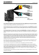
DATABASE CONFIGURATION The GWnet address is used to specify the network configuration LMS should deal with and the addresses to which it will find the various devices. LMS supports three basic network configuration: A zero level network - there is no gateway and the control panel(s) are directly connected to the LMSmodular station. The connection must be point to point, i.e. only one serial line can be used.
DATABASE CONFIGURATION GATEWAY GATEWAY GATEWAY Two level network One level network B one level network - there is only one gateway, directly connected to the LMS station, that collects and sends data to field control panels (see Configuration A) C two level network - there could be two or more gateways. One of them is connected directly to the LMS station (Concentrator), the others (secondary Gateways) are connected to this Gateway that acts as a concentrator (see Configuration A) .
DATABASE CONFIGURATION Cases (a) and (c) are equivalent With zero level network, Parameters 2, 3 and 4 must be set to 0. If you are configuring a subsystem in Configuration A (one level network) or a subsystem in Configuration B (two level network) and it is connected to the Concentrator ♦ Parameter 1 must be set to the proper channel address configured ♦ Parameter 2 must be set to 0 ♦ Parameter 3 must be set to 0 ♦ set Parameter 4 (Subsystem line) to the subsystem's network address.
DATABASE CONFIGURATION • • • • • • It is the security level the operator should have to access the subsystem during subsystem management. The value range is from 0 to 9 and suggested values are listed in Table 4.21. ASSOCIATED PAGE 1 ASSOCIATED PAGE 2 ASSOCIATED PAGE 3 ASSOCIATED PAGE 4 ASSOCIATED PAGE 5 The five graphic pages are associated to this subsystem and displayed during subsystem management. If no Graphic Station is configured, the five of them are shown on the LMS Operating Station.
DATABASE CONFIGURATION Only the following subsystems have subtypes associated to them. All of the other devices will leave the "Subtype" field set to 0. Warnings SUBTYPE CODE 100 points 0 200 points 1 300 points 2 400 points 3 500 points 4 600 points 5 700 points 6 800 points 7 Table 4.5 - Warnings subtypes You cannot modify a warning subsystem, neither add new points.
DATABASE CONFIGURATION System Diagnostic SUBTYPE Diagnostic LMS station CODE 0 Table 4.8 - System diagnostic subtypes Cerberus Gateways SUBTYPE CODE MK7022/CK100 0 CK11 Gateway for CC-11 1 Table 4.9 - Cerberus Gateways subtypes SE902S SUBTYPE CODE 2 Doors, 2 VIP, 1 MI6 0 2 Doors, 2 VIP, 4 MI6 1 2 Doors, 2 VIP, 8 MI6 2 2 Doors, 2 VIP, 8 MI6, 4 RO4 3 Table 4.
DATABASE CONFIGURATION CDSS (Cerberus Dati Standard System) SUBTYPE CODE 25 points 0 50 points 1 100 points 2 200 points 3 400 points 4 600 points 5 800 points 6 1000 points 7 Table 4.12 - CDSS subtypes SE422 SUBTYPE CODE 2 Doors, 2 VIP 0 2 Doors, 2 VIP, 4 422MI 1 2 Doors, 2 VIP, 8 422MI 2 2 Doors, 2 VIP, 8 422MI, 4 422RO 3 Table 4.
DATABASE CONFIGURATION Wireless - WSS net component SUBTYPE CODE Node 0 RX 1 TX - 260 points 2 TX - 510 points 3 TX - 1010 points 4 TX - 1510 points 5 TX - 2010 points 6 TX - 2510 points 7 Table 4.16 - Wireless - WSS net component Burle SUBTYPE CODE Burle 64 alarms 0 Burle 128 alarms 1 Burle 256 alarms 2 Table 4.
DATABASE CONFIGURATION Time-out values SUBSYSTEM LMS SUGGESTED VALUE (Seconds) 5 Cerberus Dati Gateways GW-xx GUARD TOUR CMX 10 CDSS CCTV WIRELESS - WSS NET COMPONENT CBA GENERIC SUBSYSTEMS BURLE 20 CZ10 CZ12 CS4 STT Cerberus Gateways (MK7022, CK100, CK11) SE902S CC-11 SE422 CC-60 SE818 NCRS-FSS 90 Table 4.20 - Suggested time-out values e1109a.doc Data and design subject to change without notice. Supply subject to availability © Copyright by CERBERUS AG, CH-8708 Männedorf, Switzerland 1995 09.
DATABASE CONFIGURATION Security level values SUBSYSTEM CCTV SUGGESTED VALUE 4 BURLE CMX 5 WIRELESS - WSS NET COMPONENT STT 6 CZ10 CBA Cerberus Gateways (MK7022, CK100, CK11) CC-60 CZ12 7 CS4 GUARD TOUR SE902S CC-11 SE422 SE818 Cerberus Dati Gateways GW-xx 9 LMS WARNINGS Table 4.21 - Suggested security level values When all of the necessary information has been completed, press Ctrl-End to record the information. The system will ask you to confirm: Confirm ? (Y/N) Type Y.
DATABASE CONFIGURATION PRINT allows you to print the configuration information of the points. When PRINT is selected, a secondary menu appears, GLOBAL PRINT SELECTED PRINT asking whether you wish to print the information about all points (GLOBAL PRINT) or only about one (SELECTED PRINT). The printout contains the information listed in Par. 4.2.4 where print option is described. THE POINTS' LIST For a user on the operator level, the list is simply a list of numbers and point descriptions.
DATABASE CONFIGURATION The meaning of the row of abbreviations is as follows: Subs Des Tre Op1...Op3 Sc Rk Rea number of the associated subsystem number of status description table number of treatment table option number, from 1 to 3 point is in (0) or out of (1) scan risk class reaction table number The numbers and abbreviations that appear in the list correspond to fields in the configuration form. The meaning of the information will be explained by the use of the following example.
DATABASE CONFIGURATION A user on the technical level will have access to all the fields in this form, but a user on operator-level will only be able to alter the point description and the risk class. Most of the information is already configured and should not be changed. The most important information to insert at this stage are the numbers of the treatment pages. Once they are created, their numbers should be recorded here. • • • • • • • • • • e1109a.
DATABASE CONFIGURATION commands. Within the context of the specified topic, DDE item is the name of the specific piece of information that LMS wants to receive. In a DDE conversation with an Excel sheet, for instance, the DDE item could be the cell name or address. DDE type: this parameter is used to set the type of advise loop between LMS and the DDE server application. When a DDE conversation is activated, the server (i.e.
DATABASE CONFIGURATION A list of operators appears, showing their number, name, and log- in code. In the menu area, these choices appear: MODIFY APPEND PRINT EXIT EXIT returns to the Database Configurator's principal menu. PRINT produces a secondary menu, which asks whether all of the operator information should be printed, or only that of one operator. If you choose to print the information of one operator, the operator currently highlighted will be printed.
DATABASE CONFIGURATION • AUTOLOGOUT TIME: this field sets the time for automatic logout of the operator, if any. If the field is set to 0, the automatic logout is disabled. You can however set the field to a value between 5 and 999. The number is the time, in minutes, the system waits for any user interaction (keyboard or mouse activities). If no interaction takes place, the system performs an automatic logout of the operator.
DATABASE CONFIGURATION MODIFY lets you change the channel settings. Remember to perform a consistency check after any modification to the channel data. This precaution avoids inconsistencies such those generated by the configuration of a channel with a subsystem type that is subsequently deleted from the LMSmodular database. The 0 channel must be used first. You cannot configure LMSmodular without configuring the zero channel.
DATABASE CONFIGURATION • • Ciphered GW link: it is used to connect CDI GW on which the ciphering procedure is enabled. DDE link: virtual link used to communicate with other Windows applications that use the DDE protocol. When the DDE link is configured, you must key in the service name, i.e. the name of the Windows application that acts as a server to LMS. For instance, if you wish to activate a DDE conversation with Excel, you must fill this field with the EXE filename, i.e. EXCEL.
DATABASE CONFIGURATION Fig. 4.11 "Hot stand by" means here a network architecture type based on a hot standby configuration, as shown in Fig. 4.12. In the hot standby configuration LMSmodular receives data and sends commands to the subsystems connected to it using two independent paths. The two paths go through two different Gateways GW-00, that are linked to two different coupled channels.
DATABASE CONFIGURATION GW-00 GW-00 0-5-7-31 1-5-7-31 GW-01 GW-01 0-x1-y1 -31 0-x2-y2 -31 CZxx CZxx 0-x1-y1 -z1 0-x2-y2 -z2 Fig. 4.12 4.3 Internal Data When subsystems are configured (Par. 4.1), points are automatically created and configured. Each different type of device receives an appropriate arrangement of points. At the same time, the points are connected with Description and Treatment Tables that already come pre-configured in LMS.
DATABASE CONFIGURATION Treatment tables determine which point values are critical values, what type of event these critical values give rise to, and how the events will be recorded. Description tables determine what message will be given to the operator in his list of events, and how the status of the point will be presented in video pages. Multistation is an option used when more than one PC is connected to the Gateway to configure the message exchange between these operating stations.
DATABASE CONFIGURATION NUMBER COLOR 0 green 1 white 2 sky-blue 3 yellow 4 magenta 5 red 6 flashing white 7 flashing sky-blue 8 flashing yellow 9 flashing magenta 10 flashing red Table 4.27 Fig. 4.13 4.3.2 Treatment Tables Treatment tables are tables for classes of events and describe the actions that have to be undertaken when a change of status of a point associated to that treatment table happens.
DATABASE CONFIGURATION EXIT returns to the principal menu of the Database Configurator. PRINT allows you to print the treatment tables. When PRINT is selected, a secondary menu appears, GLOBAL PRINT SELECTED PRINT asking whether you wish to print the information about all tables (GLOBAL PRINT) or only about the highlighted one (SELECTED PRINT). The printout lists on two lines the 16 triplets of flags, each one corresponding to an event code.
DATABASE CONFIGURATION Fig. 4.14 4.3.3 Multistation The multistation configuration lets you connect two or more PC running LMS to the same gateway network. By this way you can for instance separate the management of different systems (e.g. fire and intrusion detection) on two different operating stations in front of which sit operators with different skills. An other possible use of the multistation architecture is in redundant configuration, in which one PC acts as a backup to the other.
DATABASE CONFIGURATION network address 23 network address 24 network address 25 master slave slave 1 2 3 GW-0X CZ xx CZ xx CZ xx Fig. 4.15 The master station synchronizes the system. It sends the date an time to the gateway and to other stations using the proper command. The slave station cannot send date and time. The partially master station sends date and time to the gateways and panels of which it is master.
DATABASE CONFIGURATION The options available from the secondary menu are: MODIFY PRINT EXIT PRINT transfers on paper the connection table displayed on the screen. MODIFY lets you change the setting (Fig. 4.17). The connection table can be enabled or disabled as a whole by setting the flag in the first field, "Enable". If you key in Y, the operating station will communicate in the way defined by the table, otherwise the operating station will act independently, no matter what the table contains.
DATABASE CONFIGURATION PRINT EXIT EXIT returns to the principal menu of the Database Configurator. PRINT allows you to print the reaction tables. When PRINT is selected, a secondary menu appears, GLOBAL PRINT SELECTED PRINT asking whether you wish to print the information about all tables (GLOBAL PRINT) or only about the highlighted one (SELECTED PRINT). MODIFY allows you to change the already configured reaction tables data, while APPEND creates a new reaction table. Using APPEND, the screen shown in Fig.
DATABASE CONFIGURATION Fig. 4.19 To configure a reaction table you have to: 1. 2. 3. 4. configure the sequences that will be used in the reaction table fill in the reaction table description configure for each point status which sequence will be run insert the reaction table number in the proper field during point configuration 4.4 SYSTEM LMS The customization of LMS can be completed with the configuration of sequences, time programs and warnings.
DATABASE CONFIGURATION 1. 1. 1. they can be launched manually, from a video page. For instance, you can display on a specific event (the detection of a person at the front door by an infrared sensor) a treatment page with a command. The command can activate a sequence that unlocks the front door, locks the hall door and temporarily disables the alarm in the hall.
DATABASE CONFIGURATION decrements of one unit the point value. CALL let you execute an other sequence - when the called sequence stops, the control returns to the calling sequence. FOR and NEXT are used to execute repeatedly the instructions enclosed between them. Look at your list of tasks, and think: what must be done to the points to make these things happen? Then use the macros, the list of points, and the list of commands to make it happen. The example given below will help you see how this is done.
DATABASE CONFIGURATION If you are adding a new sequence and you choose APPEND, a secondary menu opens: NEW SEQUENCE COPY FROM NEW SEQUENCE starts a brand new sequence, while COPY FROM lets you pick up a previously configured sequence that you can modify and adapt to your purposes. In any case, you are prompted for a sequence descriptive text, up to 30 characters long. This name should remind you the sequence's purpose.
DATABASE CONFIGURATION The macro language Sequences are written in a macro language that consists of thirteen commands and nine kind of parameters.
DATABASE CONFIGURATION COM Sends commands to subsystems. The first field of this instruction is the Subsystem number to which the command has to be sent. Then you have to type the Command number (please refer to the Configuration Reference manual). Each command can have up to 5 parameters and these are the next fields displayed. Each type of subsystem has its own commands.
DATABASE CONFIGURATION INCP Increments the point value of 1 unit. This instruction requires three parameters: the first one is the subsystem number, the second is the point number and the third is the treatment code (see Table 4.32 for the acceptable values). NEXT Ends a FOR loop. NOP Does not execute any operation; it simply passes to the next instruction. You will note that every new sequence is composed entirely of NOP instructions.
DATABASE CONFIGURATION We want to write a sequence that performs the following tasks: check the value of group 1, point 16 of a CZ10 if it is different from normal status sound a siren wait 5 minutes to let the point return to its normal status If the status is still not normal the automatic dialer is triggered wait five seconds the dialer returns to normal status The siren is silenced and the sequence ends else then the siren is silenced the sequence ends Here there is the sequence that does what we want:
DATABASE CONFIGURATION If the last "IF" test proved negative (i.e. if the point 4 of subsystem 7 was not in its normal status, meaning that the push-button was pressed) the sequence would have skipped to this line. COM 7, 3, 1, 0, 0, 0, 0 Send command no. 3 to output no. 1 of subsystem no. 7. Command no. 3 is "deactivate output" - in this case, it silences the siren. ENDIF If the first IF proved negative, i.e.
DATABASE CONFIGURATION Fig. 4.22 Then, you must input the number of sequences that compose this time program. You are requested to confirm the data you keyed in and then a new screen is displayed. The information shown are as follows: • Hour and Minute indicate the time at which the sequence should start • Sequence Number is the record number of one of the configured sequences. If you press F1 a list of configured sequences is displayed.
DATABASE CONFIGURATION Fig. 4.23 4.4.5 Warnings A warning is a set of up to five video pages that appear in the work area of an LMS station at a pre-set time. There are two kinds of warning: Single Warnings, which appear only once, and Periodic Warnings, which appear at intervals. They may also appear at irregular intervals. Both kind of warnings use a subsystem (Warnings) that is built in LMS : it cannot be created or deleted.
DATABASE CONFIGURATION APPEND DELETE OLDS PRINT EXIT EXIT returns to the Database Configurator's principal menu. PRINT produces a print-out of the configuration information of the warnings. A secondary menu will ask whether you would like to print the information on all of the warnings (GLOBAL PRINT), or only on one (SELECTED PRINT). If you decide to print only one, the highlighted warning will be printed.
DATABASE CONFIGURATION PERIODIC WARNINGS From the main menu, select SYSTEM LMS, then PERIODIC WARNINGS from the secondary menu that appears. The list of periodic warnings, i.e. of warnings that are issued every day at the pre-set hour, appears in the work area. Each entry will show the number and title of the warning, and the number of warnings contained in the periodic warning.
DATABASE CONFIGURATION Fig. 4.26 The fields that appear in the work area prompt you for a description of the warning (up to 30 characters), and for the number of warnings associated to this periodic warning. After you confirm that the information is correct, the warnings in the program will appear, one at a time (Fig. 4.26).
DATABASE CONFIGURATION The typical week "Typical week" tells LMS how to handle the different days in a week. This allows to set the system behavior according to the different habits you can have in various country. While in the western world the usual weekly resting day is Sunday, in other country it could be Saturday or Friday. By properly setting the typical week, you can deal with these differences, as well as with working habits of different companies.
DATABASE CONFIGURATION 4.4.7 Holidays The Holiday configurator works in a very similar way to the typical week. However, it lists individual days - days that are exceptions to the programs requested in the typical week. Select SYSTEM LMS from the main menu, then HOLIDAYS from the secondary menu that appears. The list of holidays appears, and each entry shows all of its configuration information in an abbreviated form.
DATABASE CONFIGURATION 4.4.8 Daylight Saving time This feature lets you define in advance the day and the hour at which the daylight saving time begins and ends. The behavior of LMS is affected also by the software option number 16, that defines if LMS will look up at the data entered, will use a standard definition for daylight saving time (see Par. 4.4.8) or it will not manage the daylight saving time at all.
DATABASE CONFIGURATION Primary and Secondary menu configuration These two options are used to configure the LMS monitoring environment menus. They let you set the menu option highlighted by default when you access the menu and the access level of each menu item. The Primary menu configuration deals with the menus available through the buttons always displayed on the screen, such as the TOOLS button.
DATABASE CONFIGURATION Fig. 4.31 4.4.10 Software Options Accessing the Software Options configuration takes you to a list that contains the parameters that affect the system behavior. The current choices (Yes/No or a numerical parameter) are displayed at the right of each line. The configuration package is shared by LMS and CMS. The L or C character shown between square brackets means if that software option is meaningful for LMS, CMS or both.
DATABASE CONFIGURATION Fig. 4.32 Fig. 4.33 Here below are listed and described the software options with their meaning. Port of logging Printer(LPTx). The logging printer is the printer that records on paper all the operator actions, events and system activities when LMS is running. This software option lets you configure the parallel port to which the printer is connected. The following values are accepted by the system: e1109a.doc Data and design subject to change without notice.
DATABASE CONFIGURATION PORT PARAMETER not configured 0 LPT1: 1 LPT2: 2 LPT3: 3 Table 4.33 Port graphics printer (LPTx) The graphic printer is the printer on which you can print the video treatment pages, for documentation purposes or to revise and correct them off-line. This software option lets you configure the parallel port to which the graphic printer is connected. The following values are accepted by the system: PORT PARAMETER not configured 0 LPT1: 1 LPT2: 2 LPT3: 3 Table 4.
DATABASE CONFIGURATION NOP operator). The default value for this software option is N: the operator, whatever his access level is, must log in to use LMS. Station active without operator When this software option is enabled (i.e. the flag is set to Y) the five event windows and the external horn will function even when no operator is logged on to the system. The default value for this software option is N. Error Sensitivity This software option is used during system test.
DATABASE CONFIGURATION Daylight saving time manag. It is used to define the pattern for the daylight saving time yearly changes. If it is set o 0, no matter which dates are configured in the database, the daylight saving time is not handled by LMS. If the flag is set to 1, the European rule is followed, i.e. the time is changed the last Sunday of March (the time is set 1 hour forward) and the last Sunday of September (the time is set 1 hour backward).
DATABASE CONFIGURATION Subsystems Checking points Checking Point Addrs. At the end of the consistency check, the following message is displayed: END OF CHECK, PRESS ANY KEY TO CONTINUE Esc will stop the test at any point. However, the test runs very quickly. It tests for the existence and integrity of all the elements named in the hierarchy of sites, systems, subsystems, and points. When you press the Esc key, the window disappears from the work area, and the main menu reappears.
DATABASE CONFIGURATION Fig. 4.34 80[145] Data and design subject to change without notice. Supply subject to availability © Copyright by CERBERUS AG, CH-8708 Männedorf, Switzerland 1995 09.95 e1109a.
APPLICATION CONFIGURATION 5. APPLICATION CONFIGURATION The application configurator lets you define a set of Windows programs that can be accessed from inside the LMS monitoring environment. As you should know, LMSmodular completely takes up the control of your PC. When you are in the LMSmodular environment, you can access only those functions the system manager defined for each operator's access level.
APPLICATION CONFIGURATION 5.1 How to configure an application APPEND adds a new application and MODIFY lets you change the settings of an existing application. When you add a new application or you modify the operating parameters of an existing one, you are presented with the same template, shown in Fig. 5.2 Fig. 5.2 The first field lets you key in a descriptive name for the application you are configuring. This name is shown during LMS operation to recall the application.
APPLICATION CONFIGURATION The next field in the template is labeled “Privileged”. This flag lets you define the application behavior when an event arise. LMSmodular is designed for maximum security, and therefore the Windows applications are confined to the screen work area. This leaves enough room on the screen to display permanently the events lamps, that show the number of events active in the system.
PAGE CONFIGURATION 6. PAGE CONFIGURATION 6.1 Introduction Video pages help the operator in performing his job and make LMS more effective. Video pages appear in the work area of LMS. They supply information, diagrams, and maps, and they provide the means of viewing system status and sending commands to subsystems. Video pages are created and displayed using a VGA graphics and they allow to describe the site layout and the points location in the most effective way.
PAGE CONFIGURATION same name as the subsystem. The LMS operators never see the index. They see the background and the foreground of the page. • the foreground of the page is the dynamic part. It changes because it interacts with the security devices in the field. The foreground is where the status of points are displayed, and where the means of sending commands are made available. • the background is the static part of the page. It never changes. It contains information and diagrams.
PAGE CONFIGURATION Fig. 6.4 To the left of the menu area, there is the HELP target. The HELP function can be activated from any menu by selecting this target with the mouse or by pressing the key F1. The help provides screens containing information related to the function from which it is called. The help screens appear in the work area. To exit the help function, press Esc or use the mouse to select the ESCAPE target on the help screen.
PAGE CONFIGURATION FROM...TO prints the configuration information on a range of pages. When this function is selected, a dialog box appears in the work area in which you can specify the first and last pages that you want printed. PAGE SELECTION presents a secondary menu with three choices: GROUPS PAGES # PAGE GROUPS presents a dialog box in the work area, such the one shown in Fig. 6.5. Fig. 6.5 Select one of the groups either with the mouse or by moving the highlight with the arrow keys and pressing Ret.
PAGE CONFIGURATION If the number you typed corresponds to an already created page, that page will appear in the work area. If the number you typed is free, the system will create a page, and this process is described in the next paragraph. 6.4 How to create a new page First step is to add an item to the page index, so that the new page you are going to configure could be correctly filed among the others. So choose NUMBER from the PAGE SELECTION menu described in Par. 6.
PAGE CONFIGURATION How to use the graphical editor CONFIGURE presents a secondary menu: BACKGROUND FOREGROUND MODIFY INDEX COPY FROM COPY FROM is a useful tool that let you make a copy of another, previously configured, page. When it is selected, the window PAGE SELECTION appears, containing the names of all the pages. Choose a page, and a copy of that page will appear in the work area.
PAGE CONFIGURATION Fig. 6.6 The targets under the page are the available colors; the target on the extreme left indicates the selected color. The center of this target indicates the foreground color; the margin indicates the background color. To change the colors used for foreground and background among those available from the color palette, click on the inside target (if you want to change the foreground color) and then click over the color you wish.
PAGE CONFIGURATION draw a straight line. Select this target and then use the mouse to point to the e starting and ending points of the line. draw an empty box between two opposite corners. Select this target, then use the mouse to indicate two corners of a box of any dimension. draw a filled box between two opposite corners. Same as the previous function. draw an empty circle with center and radius. Use the mouse to indicate the center and edge of a circle. draw a filled circle with center and radius.
PAGE CONFIGURATION sets a invisible grid with wide spacing to which the drawing tools in use snaps sets an invisible grid with thick spacing to which the drawing tools in use snaps exit the background configuration mode After exiting the configuration mode and the configuration menu, the question appears: Type Y to confirm and save the work done. If you type N, all your work will be discarded. 6.6.
PAGE CONFIGURATION Fig. 6.7 Representation is the type of representation: A for alphanumeric, G for graphic. If you choose alphanumeric representation, the status of the point will be displayed according to the Description Table (see Par. 4.3.1). You will need to leave 10 spaces free for the display of status. Leave the "Symbol" field blank if you have chosen alphanumeric representation. If you choose graphic representation, you must type the number of the symbol in the "Symbol" field.
PAGE CONFIGURATION Pages can be configured to send both commands and sequences to the subsystems. The command codes for the various subsystems are given in the LMSmodular Configuration Reference manual. Sequences are configured by you (see Par. 4.4 for more information). Type indicates whether a command (C) or sequence (S) is being sent. Subsystem Index is the number of the subsystem to which the command or sequence is being sent. Command/Sequence No. is the number of the command or sequence.
PAGE CONFIGURATION 6.7 Graphic Station Maps The Graphic Station maps are created using the page configuration exactly as any other page. They are different only because are configured as the fifth page for a subsystem or point’ s event. Two pages have a particular meaning: • Page 998. This page is displayed when no operator is logged in on the LMS Operating Station. Usually this page contains the company logo. Fig. 6.9 shows an example of such a page. • Page 999.
UTILITY 7. UTILITY When the configuration phase is completed, it is wise to make a copy of the Station configuration on a floppy disk, because data can be damaged by equipment failure, power fluctuations, carelessness, or accident. A backup will save you many precious hours of work, if you have to restore the LMS installation. The backup program in the Integrator Menu records all the LMS data files of the Main Operating Station on a floppy.
UTILITY 7.1 Making a backup To perform the operations described below, you will need one or more new and formatted floppy disks. Select BACKUP from the UTILITY secondary menu. A message is displayed, that request you to insert a blank and formatted diskette in drive A: Insert the disk and press any key. The backup will immediately begin and a series of messages, showing the operation in progress, is displayed.
UTILITY Fig. 7.3 7.2 Restoring the data This procedure restores the configuration to the hard disk from the floppy disk. You will need the floppy disk, produced by the backup procedure of LMSmodular or by backups by previous versions of LMS (versions 2.3 and 2.4x are supported) that contain the configuration files. Select RESTORE from the UTILITY secondary menu. You are prompted to insert in the drive A: the last diskette that contains the backup files.
UTILITY Fig. 7.4 7.3 Import pictures The third option of the UTILITY menu is PICTURE. Accessing this option you can copy the pictures generated by whatever mean into the directory used by LMS during Video Page configuration. The following file formats are handled by LMSmodular: • • • • • • BMP - The BMP format is the internal picture file format used by Windows and is also supported in the OS/2 environment. DIB - a bitmap file format supported by the Paintbrush package supplied with Windows.
UTILITY Fig. 7.5 7.4 Import points The fourth option of the UTILITY menu is IMPORT POINTS. Accessing this option you can import in the LMSmodular database the point configuration data generated using either a spreadsheet that could save data into the "text and commas" format, or the configuration tools for the CZ10, or coming from an other LMS database of from a CS11 metafile. When you access the Import points utility, a main menu is shown in the menu area of the screen.
UTILITY The first option, SPR0, lets you import data generated by a spreadsheet in the format of text separated by commas. This format requires that the data contained into a cell are organized by rows. Each cell contents is separated by the following by a comma (,). The end of a row is marked by CRLF characters. Using this file format you can import all the parameters that could be associated to each point. The directory \COPAVI\TUTORIAL contains an example of worksheet. The file name is PUL_TMPL.
UTILITY SWE11 PCX-DataBase eg. DZR001.DAT CC11LIST Meta-File Foreign Host LMSimport eg. SITE.TXT NISE The procedure sets in the point database both the point texts and the relationships between points. All the LMS points that do not have a correspondent object in the CC11 list are set out of scan automatically. The import procedure can be repeated as many times as necessary.
UTILITY The software package does not perform any check on the correctness of the data. An error could occur while you execute the import procedure. 7.4.3 Select Destination When you select this option, a list of configured subsystems is shown. From this list you have to pick the subsystem to which you wish to add the points to be imported. 7.4.4 Run Import This option actually performs the import of points from the selected file, that should be in the specified format, into the selected subsystem.
UTILITY 7.5.1 Select Source This option lets you define the directory that contains the pages to be imported. The pages' files to be imported must have extension SCF. Fig. 7.7 7.5.
UTILITY the import software will create the page 31 in the current LMS installation. The page 31 will contain the same information that were present in the page 12 of the old installation, but it will be accessed in the current LMS installation with the number 31, it will be named "Test" and it will belong to the group "Test Group". Fig. 7.8 7.5.
UTILITY Fig. 7.9 During the import procedure, the points read and the corresponding LMS point assigned are displayed, as well as the point description. Fig. 7.10 7.6 Export points The sixth option of the UTILITY menu is EXPORT POINTS. Accessing this option you can export the point configuration data of the in the LMSmodular database either in a "text and commas" format or in the CZ10 readable format. e1109a.doc Data and design subject to change without notice.
UTILITY When you access the EXPORT POINTS utility, a main menu is shown in the menu area of the screen. From the main menu you can choose one of the following options SELECT FORMAT SUBSYSTEM SOURCE SELECT DESTINATION RUN EXPORT EXIT To use the export point option, you must 1. 2. configure the subsystem's point using the LMS configurator run the export procedure 7.6.
UTILITY 7.6.2 Subsystem Source When you select this option the software package displays a list of configured subsystems. You can export points only from one subsystem at a time. You can use the up and down arrows to highlight the subsystem you wish to export and then press Enter. The selected subsystem is listed in the lower part of the work area. Fig. 7.12 7.6.3 Select Destination When you select this option, you are prompted for a file name.
UTILITY Fig. 7.13 7.7 Export pages The seventh option of the UTILITY menu is EXPORT PAGES. Accessing this option you can generate a list of foreground points that were configured in the treatment pages. The list is in the SPRO format, i.e. text and commas, easily understood by a number of spreadsheets. So you can sort or print the list at your will. The list can be used just for reference, or to speed up the configuration process.
UTILITY Fig. 7.14 To use the export pages option, you must 1. choose the SELECT FORMAT option: it defines the file type for export. There are two options in the submenu: FOREGROUND SPR, that exports the foreground points in the "text and commas" format PAGES that exports the page backgrounds 2. choose the SELECT SOURCE option: it defines which foreground point pages to export. The only valid selection is ALL pages. 3.
PAK MANAGER 8. PAK MANAGER The operating station running LMSmodular v. 2.x software is enabled to actually communicate with the subsystems by the installation of the hardware key and a Product Authorization Key (PAK). The hardware key must be connected to a parallel port of each operating station connected to the system. PAK is an alphanumeric string to be entered at installation time using the PAK manager. You must enter as many PAKs as the number of modules you wish to install.
PAK MANAGER 8.1.3 Number of lines The basic module PAK contains also the information about the number of subsystems you can connect to the operating station. Each subsystem counts in general one unit. Exceptions are CMX, Westinghouse SExxx and equipment connected via NISE and FHI-PAD. • • • • Each CMX cluster, ranging from 1 to 16 units, is equal to one subsystem. SE902/422/818 are not considered in the count, i.e. they do not weight any subsystem.
PAK MANAGER Fig. 8.3 When there are PAK configured, they are listed in the upper area, that list the module name the PAK enables and the PAK itself. In the area below, there are some fields that describe the information contained in the selected PAK. The information listed are: • • • • • • software module version date capability parameters site description license number The capability describes the type of LMSmodular license you are enabling.
PAK MANAGER Fig. 8.4 8.2.1 ADD a new PAK To ADD a new PAK, you must click on the add button at the right. A dialog box (Fig. 8.5) opens, that lets you select the Module name from a drop down list. Fig. 8.5 116[145] Data and design subject to change without notice. Supply subject to availability © Copyright by CERBERUS AG, CH-8708 Männedorf, Switzerland 1995 09.95 e1109a.
PAK MANAGER Fig. 8.6 You can then type the PAK in the proper field. Remember that a PAK is 16 characters long and can contain any alphabetical character and numbers from 1 to 6. Fig. 8.7 When the fields are filled in, click on the SAVE button to record the PAK and enable the corresponding module. You can as well cancel the operation, using the CANCEL button. Either you saved or canceled the PAK, you can EXIT the dialog box with the exit button. 8.2.
PAK MANAGER Fig. 8.8 The dialog windows is basically the same for the ADD function. You can however scroll the configured PAKs using the Previous/Next and Top/Bottom buttons. The modifications can be saved or canceled - click on the Exit button to return to the PAK manager main window. 8.2.3 DELETE an existing PAK To delete a PAK, in the PAK manager main window simply select it and click on the DELETE button. You will be prompted to confirm the deletion. Fig. 8.9 You can confirm or cancel the operation.
PAK MANAGER Fig. 8.10 Insert the diskette and press any key. When the backup procedure will be completed, a message will tell you if it was successful or not. Should any error be detected, the following screen will be displayed: Fig. 8.11 If an error was detected, press any key to return to PAK manager, correct the error and re-run the backup procedure. To perform a restore, the procedure is as well simple. Click on the restore button - the following screen will appear. e1109a.
PAK MANAGER Fig. 8.12 Insert the diskette with the backed-up data on it in the disk drive and press any key. 8.2.5 Print The list of configured PAKs can be printed on paper for future reference, Simply click on the PRINT button to get a hardcopy of the PAK list. 8.2.6 Exit the PAK manager Click on the Exit button. You will be prompted to confirm your choice. Click on the YES button if your really want to leave the PAK manager environment Fig. 8.
REFERENCE GUIDE 9. REFERENCE GUIDE ACCESS THE INTEGRATOR MENU From the LMS environment, if you are a high-level user, choose ENG. TOOLS from the TOOLS menu. From the DOS environment, type the following two commands: CD \COPAVI CNF BACKGROUND DRAWING In the Page configurator, after a page has been chosen, choose CONFIGURE from the main menu, then BACKGROUND from the secondary menu that appears. Targets will appear around the work area from which you can choose colors and drawing functions.
REFERENCE GUIDE ENDIF In a sequence, this command ends an if-block. If the test statement was false, the sequence moves the next line after the ENDIF. FOREGROUND CONFIGURATION In the Page configurator, after a page has been chosen, select CONFIGURE from the main menu, then FOREGROUND from the secondary menu that appears. FOR...NEXT A couple of instructions that let you execute repeatedly the instructions enclosed between them. Up to three levels of FOR loop can be nested.
REFERENCE GUIDE IFNE In a sequence, one of the tests that can begin an if-block. It uses three parameters: 1) 2) 3) the number of a subsystem, the number of a point whose value is tested, a numeric value. If the point value is NOT equal to the number given, the commands in the if-block are executed. If they are equal, the program moves to the first line after the next ENDIF.
REFERENCE GUIDE BAUD RATE To set the baud rate for the message transfer between the PC on which LMSmodular runs and the device(s) connected to it, access CONFIGURATION from the main menu and choose DATABASE. Then select INSTALLATION and then CHANNELS. RESTORE CONFIGURATION DATA (see Data Restore) SEQUENCE CONFIGURATION Select CONFIGURATION and then DATABASE from the main menu. From the secondary menu that appears select SYSTEM LMS then SEQUENCES .
REFERENCE GUIDE TYPICAL WEEK Select CONFIGURATION from the main menu and then choose DATABASE from the pull down menu. Select SYSTEM LMS and then TYPICAL WEEK from the secondary menu that appears. WAIT In a sequence, pauses for the period of time specified by two parameters: 1) 2) e1109a.doc minutes, seconds. Data and design subject to change without notice. Supply subject to availability © Copyright by CERBERUS AG, CH-8708 Männedorf, Switzerland 1995 09.
MENU TREE STRUCTURE 10. MENU TREE STRUCTURE CONFIGURATION Database Installation Internal Data System LMS Services Denominations Sites Systems Subsystems Operators Channels Descriptions Treatments Multistation Reactions Sequences Time programs Sing.
GLOSSARY 11. GLOSSARY ABSOLUTE ADDRESS Every point in the point database is assigned a unique number by which it can be accessed. This is the absolute address. (See also Relative Address) ACCESS LEVEL A number assigned to each operator. It is invisible to the operator, but the system matches the access level and security level to establish which activities should be available to the operator.
GLOSSARY CDDL Cerberus Dati Data Link protocol. CDSF Cerberus Dati Standard Format for application messages. CDSS Cerberus Dati Standard Subsystem, a subsystem manufactured by third parties that is compliant with CDSF. CHANGE OF STATUS Any change in the value of a point. CMX An hardware device that manages both digital inputs and digital outputs (open collector and relays). It is a subsystem managed by LMS.
GLOSSARY DESCRIPTION TABLE A table in which point values are associated to specific words, which are presented on colored backgrounds. Some examples of the descriptions are: OPEN, CLOSED, ALARM, SABOTAGE. DIAGNOSTIC SUBSYSTEM A group of points related to the status of connections and faults. DIGITAL DEVICE Two-phase inputs or outputs controlled by LMS. Examples: Inputs can indicate whether a door is open or shut. Outputs can lock or unlock a gate.
GLOSSARY FSS Foreign Security System, a security system manufactured by third parties that is compliant with CDSF/CDDL specifications. GATEWAY A modular, multiprocessor electronic device that interfaces the peripheral control unites with the PC on which LMS runs. The gateway also allows subsystem interactions. GRAPHIC REPRESENTATION When, on a video page, point status is represented by symbols. These symbols are given in LMS.
GLOSSARY LOCAL ADDRESS A number used in configuring some subsystems. When several subsystems are located at the same Network Address, they are distinguished by having unique local addresses. This information is established by the person who installs the hardware. MACRO LANGUAGE A set of 13 commands and 7 parameters by which programs (sequences) can be written that test and manipulate the security devices. MAP A graphic page displayed on the Graphic Station.
GLOSSARY RESET After an event has been treated, a reset can be performed to remove the event from the list of events on the LMS video screen, and to clear the abnormal values from the points of that subsystem. A reset can be performed from the LMS terminal by some LMS operators. (See also Automatic Reset) RESPONSE TIME (see Feedback Time-out) RESTORE One of the LMS configurator functions through which configuration data files can be copied from a floppy disk and installed on the hard disk.
GLOSSARY SYSTEM Consists of all the similar devices that are necessary to carry out one homogeneous function (i.e. a fire detection system or an intrusion detection system). Systems are composed of subsystems. TARGET A small window on the video screen which executes a command or function when selected using the mouse. TIME PROGRAM A means of launching sequences at pre-set times. They associate sequences with hours of the day. Time programs are launched in turn by the calendar functions.
GLOSSARY From: ................................................... To: Customer Support Company: ................................................... CERBERUS DATI S.p.A. Address: ................................................... Via Milano, 141 City: ................................................... 20093 COLOGNO MONZESE (MI) ITALY Tel#: ................................................... Tel.#: +39 2 27.30.39.14 Fax#: ................................................... Fax.
GLOSSARY ....................................................................................................................................................... ....................................................................................................................................................... ....................................................................................................................................................... ..............................................
GLOSSARY ____________ Reserved for CERBERUS DATI Product Support Engineers ____________ Defect Repair Log Classification: Defect Identification Number: ___________________________________ Date: _________________________ Defect Severity Critical Customer is unable to use the product, resulting in a critical impact on their operation. This problem requires an immediate solution. Serious Customer is able to use the product, but is severely restricted. A temporary solution should be supplied.
GLOSSARY Defect Introduced during previous defect fix?_____________________________________________________ Test Date of Test: ______________ Tested by:__________________________ Engineering hours to test: __________ Only if Correction was not necessary Report Incorrect - not a defect: ________________________________________________________________ Defect already known, with Identification Number: : ________________________________________________ 140[145] Data and design subject to change without
INDEX 12. INDEX A Absolute address .............................................................129 Access level.........................14, 16, 17, 42, 76, 95, 129, 134 Alphanumeric keys............................................................13 Alphanumeric representation ............................94, 129, 132 Arrow keys ........................13, 14, 15, 22, 24, 25, 74, 87, 88 Attribute ....................................................................49, 129 B Background ...........
INDEX Import pages ..................................................... 97, 104, 106 Import pages ..................................................................... 97 Import pictures.............................................. 10, 18, 97, 100 Import pictures.................................................................. 97 Import point from a spreadsheet ..................................... 101 Import point from LMS database.................................... 101 Import points ..................
INDEX Subsystem Operative Status ..............................................40 Subtype .........................................................26, 31, 33, 134 SWX0..............................................................................102 Symbol ........................................................................93, 94 System.................................................................................7 System.....................................................
INDEX e1109a.doc Data and design subject to change without notice. Supply subject to availability © Copyright by CERBERUS AG, CH-8708 Männedorf, Switzerland 1995 09.