
Installation Instructions

4
Detector
wiring
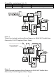
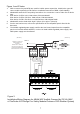
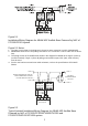
(Refer to Figures 7 and 8) Audible base Model ABHW-4SZ
should be interconnected as shown in the Installation/ Wiring
Diagrams and wired to the specific system modules and control
panels following the appropriate instructions. For operation with
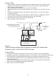
FireFinder-XLS/Desigo Fire Safety Modular/Cerberus PRO
Modular, FC2005/FC901, FC2025/FC2050/FV2025/
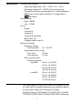
FV2050, FC922/FC924/FV922/FV924 system, note any
limitations on the number of audible bases permitted on each
notification appliance circuit or 24VDC regulated power supply,
depending on the total cable resistance and total load of each
circuit. (See ELECTRICAL RATINGS section.)
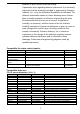
Note: Recommended wire size: 18 AWG min.; 14 AWG max.
Wire larger than 14 AWG can damage the connector.
Detector
mounting
The detector base comes from the factory prewired. All
signaling and initiating circuits are connected directly to the
back of the ABHW-4SZ audible base using the four position
terminal blocks.
Base
mounting
1. Route all wires out from the outlet box.
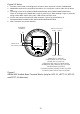
2. When the alarm LED viewing is critical, position the LED
mark on the base in the intended direction (Refer to Figure
8).
3. Make connections directly to the audible base terminals
located on the back of the base. Refer to the related
Installation/Wiring diagram.
4. After all bases are installed, check loop continuity. For
ABHW-4SZ loop continuity check, refer to the DPU or
SDPU Manual, “Testing a FireFinder-XLS Loop”.
5. If loop continuity is acceptable, proceed with detector head
installation.
Detector
placement
Use a 30 foot center spacing (900 sq ft), as a starting point
referred to in NFPA Standard 72 National Fire Alarm Code
and CAN/ULC-S524, in a detector installation layout. This
spacing is based on ideal conditions—smooth ceiling, no air
movement, and no physical obstructions.
In all installations (except in special circumstances like
computer room under floors), locate the detector on the
ceiling, a minimum of 6 inches from a side wall, or on a wall,