
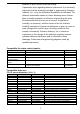
Installation Instructions

8
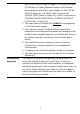
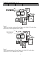
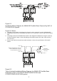
Figure 3 Notes:
1. Polarity shown in active state at terminals 1 and 2 of ABHW-4SZ and 1-4 of ZIC-4A. Proper
polarity must be maintained or audible base will not operate properly. Each audible base
must be tested to verify operation.
2. Tone selection (Refer to page 12, Note 4, for more information).
3. ABHW-4SZ terminals 5-6 are polarity insensitive. Line 1 and Line 2 can be either line of the
loop.
4. The wiring of ABHW-4SZ shown in the diagram is Style Z (Class A). It may also be wired
as Style Y (Class B).
5. ZIC-4A Notification Appliance Circuits provide 4 outputs that can be configured for Class A.
or Class B. Refer to the ZIC-4A Installation Instructions, P/N 315-033050.
6. EOL resistor, 24k ohms, 1/2 watt, 5%, P/N 140-820405.
7. NAC circuit does not provide isolation.
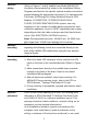
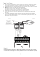
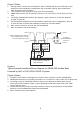
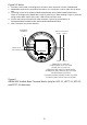
Figure 4
Typical Isolated Installation/Wiring Diagram for ABHW-4SZ Audible Base
Powered by NAC of PAD-3/PAD-4/PAD-5 System
Figure 4 Notes:
1. The NAC circuit shown in the diagram is the active state at terminal 1 and 2 of ABHW-4SZ.
2. ABHW-4SZ terminals 5-6 are polarity insensitive. Line 1 and Line 2 can be either line of device loop.
3. The wiring at NAC of PAD-3/PAD-4/PAD-5 shown in the diagram for ABHW-4SZ is Style Z
(Class A) (No EOL needed). If Style Y (Class B) wiring used at NAC output, EOL (24K, 0.5W
resistor) must be used.
4. For the max load current and max cable resistance, refer to the specifications of PAD-3/PAD-
4/PAD-5, P/N: 315-099082/315-050217/A6V101030358.
5. NAC circuit does not provide isolation.
ABHW-4SZ ABHW-4SZ
-
+
-
+
5
6
1b
1a
8 8
7 7
6 6
5 5
1 12 2
3 3
4 4
TO NEXT
ADDRESSABLE
DEVICE
LINE 2
LINE 1
LINE 2
LINE 1
FROM THE DEVICE LINE OF
THE COMPATIBLE LISTED
IN THE SPECIFICATION
NAC1
-
+
NAC1 NAC2
+
NAC2 NAC3
+
NAC3 NAC4
+
NAC4
-
-
-
NAC outputs of PAD-3/
PAD-4/PAD-5
+
-
+
-