
Installation Instructions

9
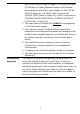
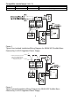
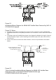
Figure 5.1
Installation/Wiring Diagram for ABHW-4SZ Audible Base Powered by NAC of
FC2005/FC901 system
Figure 5.1 Notes:
1. The NAC circuit shown in the diagram is the active state at terminal 1 and 2 of ABHW-4SZ.
2. ABHW-4SZ terminals 5-6 are polarity insensitive. Line 1 and Line 2 can be either line of device
loop.
3. The wiring at NAC of FC2005/FC901 shown in the diagram for ABHW-4S is Style Z (Class A)
(no EOL needed). If Style Y (Class B) wiring used at NAC output, EOL (24K, 0.5W resistor)
must be used.
4. For the max load current and max cable resistance, refer to the specifications of FC2005 /
FC901.
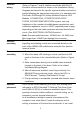
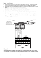
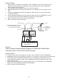
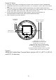
Figure 5.2
Typical Isolated Installation/Wiring Diagram for ABHW-4SZ Audible Base
Powered by NAC of FC2025/FC2050/FV2025/FV2050 and
FC922/FC924/FV922/FV924 system
ABHW-4SZABHW-4SZ
ABHW-4SZ ABHW-4SZ
-
+
-
+
5
6
1b
1a
8 8
7 7
6 6
5 5
1 12 2
3 3
4 4
TO NEXT
ADDRESSABLE
DEVICE
LINE 2
LINE 1
LINE 2
LINE 1
NAC1
2_-
NAC1
2_+
NAC1
1_-
NAC1
1_+
per Periphery
NAC outputs
FROM THE DEVICE LINE OF
THE COMPATIBLE LISTED
IN THE SPECIFICATION
+
-
+
-