FHA2054-U1 Audio transformer kit Mounting Installation A6V10590197_en--_a 2016-02-26 Building Technologies Building Technologies Division
Legal notice Legal notice Technical specifications and availability subject to change without notice. Transmittal, reproduction, dissemination and/or editing of this document as well as utilization of its contents and communication thereof to others without express authorization are prohibited. Offenders will be held liable for payment of damages. All rights created by patent grant or registration of a utility model or design patent are reserved. Issued by: Siemens Industry, Inc.
Table of contents Building Technologies Siemens Industry, Inc. 1 Description .......................................................................................... 5 2 Installation ........................................................................................... 6 3 Preparing and installing the cable ........................................................... 7 4 Views ..................................................................................................
| 16 Building Technologies A6V10590197_en--_a Siemens Industry, Inc.
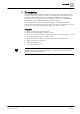
Description 1 1 Description The FHA2054 audio transformer kit is for a reliable ground disconnection of the low-level audio source in booster amplifier station EBA2001. The FHA2054 audio transformer kit is installed in booster amplifier station EBA2001 and must be connected to 'Line in' 'X4' at the booster amplifier mainboard (100 W) EBA2004. The FHA2054 comes with all individual parts for installation.
2 Installation 2 Installation 1 2 5 4 3 Figure 1: Installing the FHA2054 audio transformer kit 1 Shield connection terminal block 2 The FHA2054 audio transformer kit is mounted on the busbar 3 2x #4-40 pan-head Phillips screws, L ¼" 4 Busbar L=100 mm with 2x fastening tabs 5 2x threaded standoffs in back box 1. Plug the shield connection terminal block (1) onto the busbar (4) from above. 2.
Preparing and installing the cable 3 3 Preparing and installing the cable Preparing the external cable 30 mm / 1.18 inch 20 mm / 0.8 inch 60 mm / 2.4 inch cut shield remove insulation Figure 2: Stripping the external cable for FHA2054 w Use a twisted, shielded cable. 1. Cut open the insulation approximately 90 to 110 mm/3.5" to 4.3" from the end of the cable and remove the insulation approximately 20 mm/0.8" from the cable. 2. Strip approximately 30 mm/1.18" from the end of the cable. 3.
3 Preparing and installing the cable Laying the cable and connecting the shield 1 2 3 4 X41 X42 5 X4 6 Figure 4: Wiring of the FHA2054 audio transformer kit 1 Busbar with FHA2054 audio transformer kit mounted 2 Exposed shielding in the shield connection terminal block 3 External twisted, shielded cable to X41 4 PCB of FHA2054 audio transformer kit 5 Internal twisted cable 6 Booster amplifier mainboard (100 W) EBA2004 1.
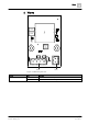
Views 4 4 Views RM1 9 C108 R102 C106 8 T101 R104 4 R101 3 C105 2 C104 C103 C107 4 1 6 L101 3 2 R103 X44 RM2 X43 Label printed acc. to ES PCBA (BOM) or DMC C102 V101 1 F101 F102 V102 C101 1 X41 Figure 5: FHA2054 print view RM3 X42 Element Des. Function Connector X41 'LINE IN', 'Low level' audio input X42 'LINE OUT', 'Low level' audio output Building Technologies 9 | 16 A6V10590197_en--_a Siemens Industry, Inc.
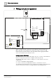
5 Wiring and pin assignments 5 Wiring and pin assignments EBA2001 Shield IN+ EOLR EOLR IN- FHA2054 LINE IN 4 3 2 1 LINE OUT X42 1 2 OUT+ OUT- EBA2004 H401 FAULT transmit LINE IN (S1601-5 ON) 1 EOLR 2 3 IN+ 4 * LINE IN X4 EOL X41 Low level audio input INEOLR Figure 6: Wiring the plug connections of the FHA2054 audio transformer kit * The audio line can be monitored by connecting an EOL resistor of 3.3 kΩ, Siemens part no. C24235-A1-K14.
Wiring and pin assignments 5 Plug connection X41, LINE IN Pin Designation Description 1 E-R Connection EOL resistance 3.3 kΩ 2 IN+ Low-level audio input + 3 IN- Low-level audio input - 4 E-R Connection EOL resistance 3.3 kΩ Permissible cable cross-section for all plug connections: 1 x 12…18 AWG or 2 x 16…18 AWG Required cable: Shielded and twisted cable; the shielding must be carried out in accordance with chapter Preparing and installing the cable [➙ 7].
6 Recommended wiring for FHA2054 6 Recommended wiring for FHA2054 The low-level audio input can1 be used for non-emergency applications such as background music or convenience paging. A wiring example is shown below.
Recommended wiring for FHA2054 FACP* voice 6 EBA2001 Low-level audio input FHA2054 EBA2004 Booster amplifier mainboard High-level audio input High-level audio output (25 V / 70 V) UL listed EBA2001 EBA2004 Booster amplifier mainboard High-level audio input High-level audio output (25 V / 70 V) EBA2001 EBA2004 Booster amplifier mainboard High-level audio input High-level audio output (25 V / 70 V) Figure 8: Recommended cascading application with low-level audio input * FACP = Fire alarm control
6 Recommended wiring for FHA2054 14 | 16 Building Technologies A6V10590197_en--_a Siemens Industry, Inc.
FCC Statement 7 7 FCC Statement WARNING Installation and usage of equipment is not in accordance with instructions manual Radiation of radio frequency energy Interference to radio communications ● Install and use equipment in accordance with instructions manual. ● Read the following information. This equipment generates, uses, and can radiate radio frequency energy and if not installed and used in accordance with the instructions manual, may cause interference to radio communications.
Issued by Siemens Industry, Inc. Building Technologies Division 8 Fernwood Road Florham Park, NJ 07932 +1 973-593-2600 www.sbt.siemens.com/FIS Document ID: A6V10590197_en--_a Edition: 2016-02-26 © Siemens Industry, Inc., 2015 Technical specifications and availability subject to change without notice. SAP order no.