
Installation Instructions


Preparing and installing the cable
3
8 | 16
Building Technologies
A6V10590197_en
--
_a
Siemens Industry, Inc.
2016
-
02
-
26
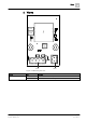
Laying the cable and connecting the shield
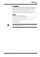
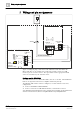
Figure 4: Wiring of the FHA2054 audio transformer kit
1 Busbar with FHA2054 audio transformer kit mounted
2 Exposed shielding in the shield connection terminal block
3 External twisted, shielded cable to X41
4 PCB of FHA2054 audio transformer kit
5 Internal twisted cable
6 Booster amplifier mainboard (100 W) EBA2004
1. Lay the external shielded cable (3) so that the exposed braid is positioned in
the shield connection terminal block (2).
2. If necessary, lay a further shielded cable through the same shield connection
terminal block.
3. Tighten the knurled screws for the shield connection terminal block to fix the
cable in place.
4. Connect the external cable (3) to the plug terminal X41, in accordance with
chapter Wiring and pin assignments [➙ 10].
5. Lay the internal cable (5) in accordance with the figure above.
6. Connect the internal cable (5) between X42 of the FHA2054 (4) and X4 of the
EBA2004 (6), in accordance with chapter Wiring and pin assignments [➙ 10].
6
2 3
1
4
X41
X42
X4
5