
Data Sheet for Product


11 / 12
Siemens RXL39.1 – Room controller CM2N3876en_10
Building Technologies 2015-12-23
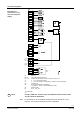
Connection diagrams
G0
G
G0
G
N1 RXL39.1
B1, B2 LG-Ni 1000 temperature sensor
D1 … D4 Volt-free contacts (window contact, occupancy sensor, etc.)
Y1 0 … 10 V valve actuator heating
Y2 0 … 10 V valve actuator cooling (heating / cooling in case of changeover)
Q1 Controlled fan
Q2 Power controller (PWM or modulating)
e.g. SEM61.4 + SEA45.1, data sheets N5102, N4937
Q3 Electric heating
B3 QAX… room unit
Twisted pair
STOP
Note!
For Q2 (1.8 kW max. resistive load), use additional external fuses of max.
10 A to protect the PCB tracks.
For information on the compatibility of field devices with the RXL39.1 room
controller, refer to the RX hardware overview, CA2N3804.
Connection of
field devices, room
unit, bus and power
supply
Note