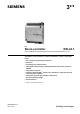
3 878 s RXL RXL24.1 Room controller Communicating controller for chilled ceiling and radiator applications CC-02 The RXL24.1 room controller is used for temperature control in individual rooms.
Application The RXL24.1 room controller is optimized for control of chilled ceiling and radiator systems in individual rooms. The application of each controller is determined by the application software. The controllers are delivered with a fixed set of applications, each of which contains various individual applications. The relevant application is selected and activated during commissioning using one of the following tools: • Synco ACS • "HandyTool" (the QAX34.
Types The RXL24.1 room controller has the following outputs: Type AC 24 V triac outputs RXL24.1 For 2 thermic valve actuators or two 3-position actuators RXZ20.1 Accessories: Terminal covers Ordering When ordering please specify the quantity, product name, type code and application group. Example: 30 Room controllers, type RXL24.1/CC-02 Compatibility The RXL24.1 room controller is compatible with field devices from Siemens Building Technologies.
The programming LED shows the operational status of the room controller as follows: Service LED Green flashing Red ON OK, device is in operation • Addressing mode (ACS / ETS) • Fault Parameter download • No supply voltage • Fault • Service LED disabled by software • Start-up (approx. 5.sec) • Fault Orange / green flashing OFF Other patterns Programming pin The programming pin is used to identify the controller in the commissioning phase.
Connection terminals The connection terminals for the bus are detachable plug-in screw-terminals. All other terminals are fixed.. Communication The RXL24.
Disposal The device is classified as waste electronic equipment in terms of the European Directive 2012/19/EU (WEEE) and should not be disposed of as unsorted municipal waste. The relevant national legal rules are to be adhered to. Regarding disposal, use the systems setup for collecting electronic waste. Observe all local and applicable laws.
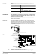
Mounting instructions 3873J07 3873J06 The room controllers can be mounted in any orientation, and fixed as follows: Rail mounting The housing base is designed for snapmounting on DIN rails, type EN50022-35 x 7.5 (can be released with a screwdriver). Surface mounting There are two drill holes for screw-mounting (see “Dimensions” for drilling template). The housing base is fitted with raised supports. Screws: Max. diameter 3.5 mm, min. length 38 mm STOP Note! Tightening torque for fixing screws max. 1.
Technical data Power supply Caution Operating data Inputs Signal inputs D1, D2 (for volt-free contacts) Measured value input B1 Outputs AC24 V triac outputs , Y1 … Y4 Ports/interfaces Interface to room unit Bus Cable connections Operating voltage Frequency Power consumption with connected field devices Internal fuse External supply line protection Control algorithm AC 24 V ± 20 % (SELV / PELV) 50/60 Hz Max. 15 VA None Fuse slow max. 10 A or Circuit breaker max.
Housing protection standard Protection standard to EN 60529 Protection class Ambient conditions Suitable for use in systems with protection class I or II Normal operation Temperature Humidity Transport Temperature Humidity Product standard EN 60730-1 Standards, directives and approvals eu.
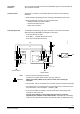
D2 Y1 G Y2 3878A08 GND 17 18 CE – D1 10 11 12 13 14 15 16 CE + 9 CE – 8 CE + 7 CP + 6 Y4 5 CP – 4 G 3 Y3 2 M 1 B1 RXL24.1 N.C. Connection terminals Bus T 2 M 1 4 3 QAX... M G G G0 G0 AC 24 V SELV / PELV 19 19 21 21 Measured value input B1 1 Measured value input for LG-Ni 1000 sensors M 2 Measured value input ground Signal inputs D1 4 Signal input GND 5 Signal ground D2 6 Signal input Triac outputs Y1 7 AC 24 V, 0.
Connection diagrams B1 1 M 2 D1 4 GND 5 D2 6 D2 Y1 7 Y1 G 8 Y2 9 Y2 Y3 10 Y3 G 11 Y4 12 T CP + 14 1 CE + 15 4 CE – 16 3 G0 19 G0 19 G 21 G 21 N1 GL M Y1.1 GL M Y2.1 Y4 2 CE – 18 B1 D1 CP – 13 CE + 17 3878A11 N1 Connection of field devices, room unit, bus and power supply PPS2 B2 Bus Bus AC 24 V RXL24.1 B1 LG-Ni 1000 temperature sensor D1, D2 Volt-free contacts (window contact, occupancy sensor, etc.) Y1...
Parallel connection of several thermic valve actuators Up to two thermic actuators per sequence may be connected directly to the room controller. With more than two thermic actuators, a UA1T power amplifier is required. The principle is the same for output Y2. Do not exceed the maximum simultaneous load on outputs Y1 and Y2 (max. 9.5 VA). Power consumption at input X1 of the UA1T: 0.5 VA. Mixed operation: It is not permissible to connect thermic actuators both to the controller and to the power amplifier.
Dimensions 4,4 Dimensions in mm 3,3 35,3 133,2 3873M14 Without terminal cover 3,9 1 62 51,5 5 62 3,9 1 167 35,3 3877M15 With terminal covers 112,4 107,8 13 / 14 Siemens Building Technologies RXL24.
Drilling diagram (1:1) 3873M16 39 78 3,6 43,2 86,3 Published by: Siemens Switzerland Ltd. Building Technologies Division International Headquarters Gubelstrasse 22 6301 Zug Switzerland Tel. +41 41-724 24 24 www.siemens.com/buildingtechnologies © Siemens Switzerland Ltd 2007 Delivery and technical specifications subject to change 14 / 14 Siemens Building Technologies RXL24.