DG80025 DG10025 DG12025 DG15025
1 2 1 2 3 4 5 DG ...
5 6 B A Type 7 A B C E mm mm mm mm DG 80 DG 100 DG 120 DG 150 836 841 900 988 993 900 1148 1153 300 900 1378 1383 300 1000 II
DG 120../150.. DG 80../100..
11 12 13 13.
14 15 V
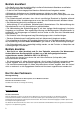
Empfohlene Anschlussarten Zweikreis / Recommended Configurations - Double-power E1 16 17 18 19 In jedem Fall kann die Variante 19 nicht mit E4-Anschluss verwendet werden. In any case, the variant 19 cannot be used with E4 connection.
Empfohlene Anschlussarten Einkreis / Boiler Betrieb Recommended Configurations - Single-power / Boiler mode operation E1 16 VII
de Sicherheitshinweise Dieses Gerät ist für den Haushalt oder für haushaltsähnliche, nicht gewerbliche Anwendungen bestimmt. Haushaltsähnliche Anwendungen umfassen z. B. die Verwendung in Mitarbeiterküchen von Läden, Büros, landwirtschaftlichen und anderen gewerblichen Betrieben, sowie die Nutzung durch Gäste von Pensionen, kleinen Hotels und ähnlichen Wohneinrichtungen. • Das Gerät wie in Text und Bild beschrieben montieren und bedienen.
Betrieb druckfest • Das Gerät nur an eine vorschriftsmäßig installierte Schutzkontakt-Steckdose anschließen. Kein Verlängerungskabel verwenden. • Es darf nur ein baumustergeprüftes Membran-Sicherheitsventil eingebaut werden. • Während des Aufheizens muss Ausdehnungswasser sichtbar aus dem Ablauf des Sicherheitsventils tropfen. Das Auslaufrohr des Sicherheitsventils muss zur Atmosphäre hin offen gelassen werden.
Sicherheitsventil-Kombination AK030300 bzw. Sicherheitsventil-Kombination mit Druckminderventil AK040300 können mit handelsüblichem Thermostat - Vormischer montiert werden. Hinweis: Nach dem Energie-Einspargesetz muss bei mehr als 5 m langen Warmwasser-Leitungen die Temperatur im Leitungsnetz auf 60ºC begrenzt werden.
Wird die Taste Schnellheizen betätigt heizt das Gerät einmalig mit der eingestellten Leistung auf. Alle 6 LED Anzeigen Wärmeinhalt leuchten auf, sobald die eingestellte Temperatur erreicht wird. Das Gerät schaltet sich anschließend wieder automatisch ab. Boilerbetrieb Anschluss ohne Niedertarif-Kontakt: Das Gerät heizt im Normalfall nicht. Wird die Taste Schnellheizen betätigt heizt das Gerät einmalig mit der eingestellten Leistung auf.
Je nach Dauer der Niedertarifzeit von 8 h oder 4 h, und der angeschlossenen Leistung (siehe Anschlussarten Seite 7) den Leistungsschalter „S1“ auf der Elektronik in die richtige Positionen 5 / 6 / 7 der „Zweikreis“ Schaltung einstellen.
Technische Daten DG80025 DG10025 DG12025 DG15025 Liter 80,0 100,0 120,0 150,0 kg 106 133 162 197 Modell Inhalt Gewicht gefüllt Mpa (bar) zulässiger Betriebsüberdruck Aufheizzeit in Stunden bei Kaltwasserzulauf von ca.
Modell Boiler-Betrieb Anschließbare Leistung Absicherung 1/N/PE~230V 1/N/PE~230V 1/N/PE~230V 2kW 3kW 4kW DG80025 - DG15025 2 kW 1/N/PE~230 V // 1 x min 10 A 3 kW 1/N/PE~230 V // 1 x min 16 A 4 kW 1/N/PE~230 V // 1 x min 20 A 2/N/PE~230V 2kW 2 kW 2/N/PE~230 V // 2 x min 10 A 2/N/PE~230V 3kW 3 kW 2/N/PE~230 V // 2 x min 10 A 2/N/PE~230V 3/N/PE~230V 4kW 2kW 6 kW 2/N/PE~230 V // 2 x min 16 A 2 kW 3/N/PE~230 V // 3 x min 10 A 3/N/PE~230V 3kW 3 kW 3/N/PE~230 V // 3 x min 10 A 3/N/PE~230V 6kW 6
Anzeigelampe (LED) Status Anode ein ein Service Stark Heizung blinken blinken aus aus Wärmeinhaltsanzeige Lampen (LED) Ursache / Fehler Behebung Wer 1 2 3 4 5 6 siehe Elektronik ist intern gesperrt, 15 Minuten warten, ein ein unten - ein ein Interner Eletronikfehler dann Reset starten (*) ein - ein - siehe unten (*) siehe unten (*) - Der Speicher hat ohne - ein Wasserfüllung aufgeheizt Warmwasser- ein - Temperatur im Speicher zu hoch Schalten Sie das Gerät aus.
Für Benutzer und Fachmann Gebrauchsanleitung Bevor Sie das Gerät benutzen, lesen Sie bitte sorgfaltig diese Gebrauchsanleitung! Sicherheitshinweise • Dieses Gerät ist für den Haushalt oder für haushaltsähnliche, nicht-gewerbliche Anwendungen bestimmt. Haushaltsähnliche Anwendungen umfassen z. B. die Verwendung in Mitarbeiterküchen von Läden, Büros, landwirtschaftlichen und anderen gewerblichen Betrieben, sowie die Nutzung durch Gäste von Pensionen, kleinen Hotels und ähnlichen Wohneinrichtungen.
Ihr neues Gerät Die Warmwasser Wandspeicher DG80025 – DG15025 mit elektronischer Regelung sind für die Erwärmung von Trinkwasser nach DIN 1988 vorgesehen. Sie können bedarfsgerecht Warmwasser bis 85°C bereitstellen und je nach Betriebsweise eine oder mehrere Zapfstellen (Entnahmestellen) versorgen. Das Wasser wird elektrisch aufgeheizt. Auf der Bedienblende wird die aktuell verfügbare Warmwassermenge durch 6 LEDs angezeigt.
LED Anzeige Anode und Service Im Normalbetrieb leuchtet die LED „Anode“ konstant, die LED „Service" ist aus. Blinkt eine der beiden LEDs, zeigt das einen „Fehlerzustand“ an. Bitte zuerst das Gerät zurücksetzen ➜ RESET, dazu wie folgt vorgehen: Zuerst den Drehknopf auf die Stellung ” ” drehen Anschließend die Schnellheiztaste drücken. Wenn die Ursache des „Fehlerzustands“ unmittelbar nach dem Zurücksetzen nicht mehr besteht, setzt das Gerät wieder seine normale Betriebs-Funktion fort.
en Safety information This appliance is intended for domestic use or for household-based, non-commercial applications. Household-based applications include, e.g. usage in employees catering facilities for shops, offices, agricultural and other commercial operations, as well as usage by guests of guest houses, small hotels and similar residential establishments. • Install and operate the appliance as described in the text and illustrations.
Closed water heater • Only connect the appliance to a correctly earthed electrical socket. Do not use extension cables. • Only a prototype-tested diaphragm safety valve may be installed. • During the heating process, expansion water must drip out of the safety valve outlet. The outlet pipe of the safety valve must remain open to the atmosphere. • The safety valve prevents excessive pressure from developing in the water heater during the heating process.
BZ12411 wall temperature regulator with bath spout, shower hose and hand sprinkler; or BZ11114 wall regulator with shower hose and hand sprinkler. The discharge from the fitting must always be free. Never use an aerator! A back-flow preventer is to be installed in the cold water intake. Wall Assembly (page II, diagrams 6 to 9) The assembly diagram is on the packaging. To allow for replacement of the heating flange and anti-corrosion anode, at least 500m of free space must be left underneath the reservoir.
Remove lower cap by taking the screws out (page IV, diagram 13, 13.1). Lead cable through the cable gland and cord grip and connect, then tighten the cable gland and cord grip (page V, diagram 14). Check that the system is suitable for the maximum power absorbed by the water heater (please refer to the data plate) and that the cross-section of the electrical connection cables is suitable, and no less than 2.5 mm2.
Single power Depending on the home installation, the following connection variations are possible: Refer to the connection types recommended for single power (page VII) Set power switch “S1” on the electronic board to positions 1 / 2 / 3 / 4 “single power”. Boiler mode Depending on the home installation, the following connection variations are possible: Refer to the connection types recommended for boiler switch (page VII) Set power switch “S1” on the electronic board to positions 8 / 9 / 0 “boiler mode”.
Technical Data DG80025 DG10025 DG12025 DG15025 Litres 80,0 100,0 120,0 150,0 kg 106 133 162 197 Model Volume Weight when full Mpa (bar) Maximum operating pressure Heating time in hrs, with cold water intake of ca.
Model Boiler mode operation Current limits Secure load 1/N/PE~230V 1/N/PE~230V 1/N/PE~230V 2kW 3kW 4kW DG80025 - DG15025 2 kW 1/N/PE~230 V // 1 x min 10 A 3 kW 1/N/PE~230 V // 1 x min 16 A 4 kW 1/N/PE~230 V // 1 x min 20 A 2/N/PE~230V 2kW 2 kW 2/N/PE~230 V // 2 x min 10 A 2/N/PE~230V 3kW 3 kW 2/N/PE~230 V // 2 x min 10 A 2/N/PE~230V 3/N/PE~230V 4kW 2kW 6 kW 2/N/PE~230 V // 2 x min 16 A 2 kW 3/N/PE~230 V // 3 x min 10 A 3/N/PE~230V 3kW 3 kW 3/N/PE~230 V // 3 x min 10 A 3/N/PE~230V 6kW 6 k
Display (LED) Status Anode Service Fast Heating On Flashing Off On Flashing Off Heat content display indicators (LED) Cause / Fault 1 2 3 4 5 On On See below (*) - Internal On On electronic failure - See below (*) On - - Solution Who 6 Electronic board locked, wait 15mins and then reset Technician The reservoir Turn the device off, check the cause of the water has heated On without water shortage (leakage, faulty water connection).
For Users and Technicians Instructions for Use Before you use the device, please read this instruction manual carefully! Safety advice • This device is intended for household or household-like use, not for commercial purposes. Household-like applications include, for example, use in staff kitchens of shops, offices, agricultural and other business operations, as well as use by guests in hostels, small hotels and similar living facilities.
Your new device The hot water storage units DG80025 – DG15025 with electronic control are designed for the heating of drinking water according to DIN 1988. They can provide hot water to 85°C and, depending on the mode of operation, service one or more taps (tapping points). The water is heated electrically. On the control panel the current amount of available hot water is displayed by 6 LEDs.
LED display anode and service In normal operations, the LED “anode” is constantly lit, the LED “service” is off. If one of the two LEDs flashes, this indicates an “error condition”. To begin with, please reset the device ➜ RESET. To do this, proceed as follows: Firstly turn the dial to the setting ” ”. After that, press the “fast-heating” button . If the cause of the error condition does not exist directly after the reset, the device will again return to its normal mode of function.
en Guarantee
420010633200 10/13 0615