DMS 7000 System Summary of Danger Management System DMS 7000 Section 4 System Features Section 3 Operation Section 5 Logging Section 2 Display Section 6 Networks/Communication Section 1 Background Information System Summary 1. Background Information 1.1 DMS7000 Family 1. 2 1.2 Selection Criteria 1. 3 1.3 Standard Functions 1. 4 1.4 System Capacity 1. 5 2. Display 2.1 General Description 2. 2 2.2 Text Display 2. 3 2.3 Graphic Display 2. 5 3. Operation 3.1 General Description 3. 2 3.2 MA7003 3. 3 3.
Foreword Foreword This reference document was compiled from information contained in the existing DMS7000 documentation and is not intended to replace any specific existing document, but to provide a working framework for sales/project engineering personnel.
e1103 Foreword 2
1. Background Information 1. Background Information Section Feature 1.1 DMS7000 Family 1.2 Selection Criteria 1.3 Standard Functions 1.4 System Capacity SW-Release e1103 Section 1 1.
1.
1.2 Selection Criteria Selection Criteria To simplify selection of the most suitable member of the DMS7000 family for the particular application it is helpful to answer the following questions: display type Must the display be both text and graphic or is a text display adequate? a. text only b. text + graphic no. of terminals/printers MT7003 MT7023 or MT7033 How many system consoles and printers must be provided? a. one system console and one printer only b. ≤ 4 system consoles/printers c.
1.3 Standard Functions Standard Functions As the same system software is used by all family members the only discrepancies result from hardware differences. All functions listed below are available throughout the DMS7000 family although restrictions due to shortage of disk or memory space cannot be excluded.
1.4 System Capacity System Capacity For project engineering purposes it is necessary to estimate both the RAM-requirements and the disk drive requirements of the system. RAM: available RAM Basic RAM on E2H081 processor board = 2MBytes - this may be extended in 2MByte blocks up to a max. of 14MBytes system requirements System itself requires approx.
e1103 Section 1 1.
2. Display 2. Display Section Feature 2.1 General Description 2.2 Text Display 2.3 Graphic Display SW-Release e1103 Section 2 2.
2.1 General Description Display Format The clear screen organisation is consistent throughout the DMS7000 family.
2.2 Text Display Description Event Messages are displayed in a standard 2-line text format. standard text The upper line is the Cerberus standard text derived from the message telegram and answers the question ”WHAT”. This text file may be configured as a country standard, although customer specific modifications are not supported. It comprises: Sector, Message type, Detector type.
2.2 Text Display HW-Requirements a. MA7003 with monochrome LCD b. MA7033/MT7023 with colour monitor SW-Configuration Site-specific text is defined in the Tree Editor SWE100-03 with the help of a Service-PC. Text modifications may also be made directly on the site-hardware using the on-line Text-Editor. B2Q210 or B2Q050 NEW MESSAGE A L A R M Palace Hotel, Conference Block, 7th Floor, Bar 1 4 0 0 0 3 2 FIRE General alarm autom.
2.3 Graphic Display Description A picture should be created for each node of the site-tree and includes all nodes and/or elements which are directly subordinate to it. Dynamic symbols are used to represent individual data-points (detector elements etc.) and signal the current status of the relevant element (or zone). Elements may also be operated on by selecting the symbol with the light-pen (or mouse), then picking out the required operation from the subsequently presented menu.
2.3 Graphic Display Further symbol attributes used to enhance the readability of the display: -white day operation (present) -light blue night operation (not present) -dark blue undefined state -flashing message not acknowledged -not flashing message acknowledged HW-Requirements SW-Configuration -crossed through Zone OFF, detector element OFF or detector address OFF -flashing Zone/detecor in test-mode / MA7033 (or MT7023: a. Colour Monitor 15” b.
3. Operation 3. Operation Section Feature 3.1 General Description 3.2 MA7003 3.3 MA7033/MT7023 SW-Release e1103 Section 3 3.
3.1 General Description Terminal Types Within the DMS7000-Family two types of operator console are available: MA7003 LCD-Panel for text display only MA7033 colour monitor suitable for text and graphic display. Operation All operations listed in ”General Functions” may be carried out on all DMS7000 Terminals. Operations fall into three categories: reacting to events Acknowledgement or Resetting of spontaneous events guided operation Only those operations are presented to the operator which are: a.
3.2 Operation MA7003 System Console MA7003 Basic display – ALARM – FAULT – STATUS Cursor keys – menu choice up – menu choice down – confirm choice Function keys – BUZZER OFF – ACKNOWLEDGE – RESET Destination keys – general – return – scroll up – scroll down – system overview Operation display Numeric keypad Key-switch for entering password – blocked – free – operation – fault – operation free/blocked Functions All operations listed in ”General Functions”. System Limits Text display only.
3.3 Operation MA7033 (MT7023) System Console MA7033 (or MT7023) Function keys – BUZZER OFF – ACKNOWLEDGE – RESET ÉÉ ÉÉ ÉÉ Basic display – ALARM – FAULT – STATUS Operation display – operation – fault – operation free/blocked Destination keys Numeric keypad – general – return – scroll up – scroll down – system overview for entering password Functions All operations listed in ”General Functions”.
4. DMS7000 Features 4. DMS7000 Features Section Feature SW-Release 4.1 Tree Structure 4.2 System Access 4.3 Masking System 4.4 Address Types 4.5 Catalogue of Alarm Causes 4.6 Intervention Texts 4.7 System Backup 4.8 Macro Commands e1103 Section 4 4.
4.1 Tree Structure Description All systems must be organised in a tree-like structure. This is built up on the basis of the geographical layout of the site. All elements which are to be displayed on the monitor screen and either react to changes in their status or be operated on via light-pen etc. must be included in the tree.
4.2 System Access Description System access is controlled in two ways: a. by key switches on the consoles b.
4.
4.3 Masking System Display/Operation The masks are treated like a stack of punched cards held up to the light, where light may only pass through at points where every card has a hole: similarly an operation is only available when it is not disabled on any of the masks. Operations which are excluded from a particular terminal-port cannot be accessed by any user-group at that terminal even with the highest Authorisation Level.
4.4 Address Types Description An Address Type may be allocated to each element (detector, contact etc). These address types can then be used as ”search paths” to locate groups of elements for collective operations. Functions The eight Address Types have pre-defined names (General, Organisation, Remote Transmission, Lock-Up Check.. etc). All of these except the ”General” type may be redefined according to customer requirements.
4.5 Catalogue of Alarm Causes Description When resetting an Alarm the operator can enter the cause of the alarm, selected from a pre-defined catalogue of possible causes. This information is stored together with the alarm message itself and may be used for analysis purposes at a later date (see History Printout). Functions This is an optional feature which must be activated on each system console (local system editor) as required.
4.6 Intervention Texts Description A freely definable text may be assigned to any event. When this event occurs the associated text is printed out on the specified printer(s). Functions The specified Intervention Text can be printed in one (or more) of the following cases: G ALARM G TROUBLE G STATUS In systems with DAY/NIGHT organisation this may also be specified as an additional criterion.
4.7 System Backup Description A backup copy of the system disk may be created at any time. This procedure runs in a background mode and has no effect on normal system operation. Functions The backup operation was specifically designed for hard-disk systems (as formerly a backup copy could only be created by a service technician with supplementary special-purpose hardware).
4.8 Macro Commands Description A Macro Command is a freely definable set of standard DMS7000 operator commands, which may be initiated by a single operation. Functions Macros may be defined by the operator himself or by his supervisor in an on-line editor. These Macros may subsequently be used like normal DMS7000 commands. System Limits Max. no. of Macro Commands Max. no. of command-lines per Macro Max. no.
5. Logging 5. Logging Section Feature 5.1 Event Logging 5.2 Intervention Orders 5.3 History Printout 5.4 Status Printout SW-Release e1103 Section 5 5.
5.
5.2 Intervention Orders Description An Intervention Text may be assigned to a particular event or range of events (i.e. at a higher level in the site-tree). On the occurence of such an event the relevant Intervention Text will be printed out on the specified printer(s). This text normally contains specific instructions for the Operator, Service Personnel or the Fire Department etc.
5.3 History Printout Description All event data is stored chronologically in RAM or on disk (option) At any time, a printout can be requested for a specified period of time, a specific type of event or a particular section of the site.
5.4 Status Printout Description A printout of the current status of a specified site-section may be requested at any time. Functions The extent of the Status Printout can be limited as follows: select required section of site-tree select Status Printout from Operating Field of standard screen status of all data points below level indicated in Information Field will be printed System Limits not applicable Display/Operation Selection via Status Printout in Operating FIeld of standard screen.
e1103 Section 5 5.
6. Networks/Communication 6. Networks/Communication Section Feature SW-Release 6.1 Standard Network Configurations 6.2 System Redundancy 6.3 Interface to non-Cerberus Acquisition Equipment 6.4 Gateway to non-Cerberus Evaluation Equipment e1103 Section 6 6.
6.1 Standard Network Configurations Description Two types of network are provided by Cerberus AG which allow an optimal configuration to be realised for all site-topographies: CERLOOP CERBAN for loop configurations for star configurations Standard CERLOOP-Network CZ10 Cerloop-Node CZ10 CZ10 MT70xx CZ10 CZ10 e1103 Section 6 6.
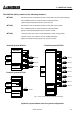
6.1 Standard Network Configurations Standard CERBAN-Network (max. configuration) 8 x CZ10 CD100-0x MT70xx 8 x CZ10 CD100-0x ”Mini-CD” MD7002 Mixed CERBAN / CERLOOP Network 8 x CZ10 CD100-0x Cerban Node 8 x CZ10 CD100-0x Cerban Node 8 x CZ10 CD100-0x Cerban Node MT70xx Cerloop-Node CERLOOP CERBAN 8 x CZ10 CD100-0x Cerban Node e1103 Section 6 6.
6.
6.2 System Redundancy Description System redundancy can be built into a DMS7000 system in a number of ways: network The data-handling procedure employed in CERLOOP permits the loop to be cut in any one place with no reduction in network functionality hot standby Two (or more) MT70xx’s may be connected into a CERLOOP network with exactly the same site-tree and mask-configurations.
6.3 Interface to non-Cerberus Acquisition Equipment Description Integration of non-Cerberus equipment may be realised in the following ways: individual I/O’s via CZ10 etc. normal inputs or control outputs of a satellite control-unit (Sector E) may be used to interface with individual sensors or actors of a ”foreign” system.
6.4 Interface to non-Cerberus Evaluation Equipment Description The Gateway MK7022 allows ”foreign” control systems to be connected into a Cerberus network (CERBAN/CERLOOP). Functions The telegram traffic through the Gateway is controlled by a communications processor, while the site-specific ”filter” is stored in an on-board EPROM containing the following information.
e1103 Section 6 6.
7. Multiplexer/Demultiplexer 7. Multiplexer/Demultiplexer Section Feature SW-Release 7.1 General Description 7.2 Sub-Unit MF7013 7.3 Sub-Unit MF7023 7.4 Command Unit MF7033 7.5 Control Unit MM7033 e1103 Section 7 7.
7.1 General Description Description The MF/MM-7000 devices are a family of programmable MUX/DMUX units which are used to provide automatic intervention on the occurence of defined events.
7.1 General Description MF7000-Elements A number of standard elements have been created to handle incoming telegrams, to facilitate the programming of these conditions and prepare outgoing telegrams. The input telegram handling routines offer the following features: - output active as long as pre-defined condition is fulfilled - special conditions: type of alarm + type of detector - special conditions: type of message (OFF, TEST, ACTIVE, TROUBLE, etc.
7.2 Sub-Unit MF7013 Description The MF7013 is built into an MC70xx and uses the processor/memory etc. of this unit. Functions see General Description. System Limits in MC7003, MC7033: max. 24 DMUX-outputs in MT7023: max. 6 DMUX-outputs no digital inputs possible full PLC-functionality (see Summary MF/MM-7000) system capacity: 10,000 load factors (see PLC-Function Handbook) Display/Operation No VDU-display. HW-Requirements MC7003, MC7033: max. 24 relay outputs (max. 30VDC/100mA) a.1 x K1G011 b.
7.3 Sub-Unit MF7023 Description The MF7023 is always built into an MC7033 and uses the processor/memory etc. of this unit. Functions see General Description. Systems Limits sum of all inputs/outputs = 192 (max. 4 MUX/DMUX-modules) full PLC-functionality (see Summary MF/MM-7000) system capacity: 20,000 load factors (see PLC-Function Handbook) Display/Operation No VDU-display. HW-Requirements MC7033 containing a max.
7.3 Command Unit MF7033 Description The MF7033 is an autonomous MUX/DMUX command unit (built in a standard 19” rack) situated in the evaluation level of a DMS-System. Functions see General Description. System Limits sum of all inputs/outputs = 576 (max. 12 MUX/DMUX-modules) full PLC-functionality (see Summary MF/MM-7000) system capacity: 20,000 load factors (see PLC-Function Handbook) approx. guidelines: 500 input telegrams 800 PLC-functions 500 output telegrams Display/Operation No VDU-display.
7.4 Control Unit MM7033 Description The MM7033 is an autonomous MUX/DMUX control unit (built in a standard 19” rack) which is situated in the acquisition level of a DMS-System. Functions see General Description. System Limits sum of all inputs/outputs = 576 (max. 12 MUX/DMUX-modules) full PLC-functionality (see Summary MF/MM-7000) system capacity: 20,000 load factors (see PLC-Function Handbook) approx.
Cerberus AG CH-8708 Männedorf Switzerland Cerberus fire and security systems safeguard life and property Document No. Manual Supersedes 06.