
User Manual
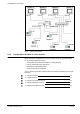

Configuring CCTV network
12
Building Technologies
048_DMS_DMS8000_Connectivity_Video_MP4.30_A6V10062457_a_en.doc
Fire Safety & Security Products
06.2010
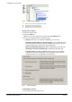
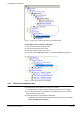
A Video-out node is automatically provided for the camera. Additional output
nodes may be added to map video distribution devices or looping connectors
that can route the video signal to multiple destinations.
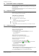
2. If required, add additional video-out nodes.
Use the command icon on the left-hand bar (Fig 8).
Fig 8 Additional camera outputs
A Select this icon to add more video-out nodes
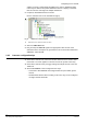
3. Select the Video Out node.
4. Drag and drop the Video In signal to the appropriate video-in node of the
destination device. Examples are given below in the sections about TELSCAN,
SIMATRIX, and SISTORE.
2.4.3 Cameras configuration tips
Check which cameras are reserved for motion detection and set them in Auto-
matic mode. The same applies to cameras reserved for system control only.
Check which cameras have pre-trigger settings and adjust the time in the SIS-
TORE tool.
Siemens IP cameras can be configured in two ways:
– Connected to SISTORE MX and configured with an input number greater
than 64.
– Networked but without video recording. In this case, they can be configured
as single-channel TELSCAN.