
User Manual


Configuring CCTV network
20
Building Technologies
048_DMS_DMS8000_Connectivity_Video_MP4.30_A6V10062457_a_en.doc
Fire Safety & Security Products
06.2010
2.7.1 Configuration checklist
Verify that you have satisfied the items needed in the first checklist before proceed-
ing to the configuration procedure that follows.
ITEMS NEEDED FOR CONFIGURATION
The SIMATRIX model: 16-4, 64.8, SYS, or NEO.
The SIMATRIX parameter settings, including complete information about the camera
inputs, monitor outputs, and alarm points (number and type).
If available, the LMS database including the SIMATRIX unit may be imported in the
stand-alone model (but not if the Video network is used).
The local address (0, 1, etc.)
The connection to the DMS: CDI-Net or NK8000
Note: CDI-Net and NK8000 require a specific line available on the gateway
Plug-ins needed:
– Plug-in #353301, which must be installed before you can configure your system
2.7.2 Configuration procedure
The following are the configuration procedures for a SIMATRIX unit:
Adding the Video Network Manager
1. Open the Composer project.
2. If not already done, add the Video Network Manager ( 2.2 at p.5).
(you may skip this point if the SIMATRIX is the only video subsystems and
you do not intend using the video network.)
Adding the folder for the SIMATRIX system
Optionally, create a folder for the SIMATRIX unit.
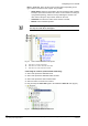
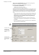
Adding the SIMATRIX node
1. Select the new folder.
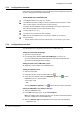
2. In the left-hand bar, select the Video folder icon
3. In the menu that appears, select the SIMATRIX “green” icon
to add a
SIMATRIX CCTV in a Video network:
See Fig 4 at p.8;
-- O
R --
Click the SIMATRIX “light blue” icon
to select the stand-alone subsystem.
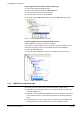
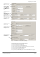
Setting the SIMATRIX Local Address and Type
1. Select the SIMATRIX node.
2. In the Node tab form (Fig 13), set the L
ocal Address.
Note: The address value should range from 0 to 15 and it should match what is
set in the configuration of the SIMATRIX unit.
3. Select the Simatrix Type (for SIMATRIX CCTV can be one of the following):
– SIMATRIX 16-4