
User Manual
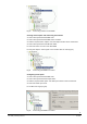
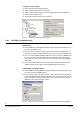
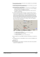
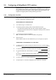
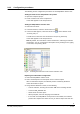
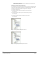
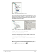

Table Of Contents

32
Building Technologies
DMS8000 Video Connectivity Configuration Guide
Fire Safety & Security Products
06.2007
2.9 Configuring a Philips/Burle CCTV switcher
DMS8000 products support the LTC8000 family of Philips/Burle CCTV switchers.
The LTC8000 family includes various switching units ranging from 8 to 4096 cam-
era inputs and from 2 to 512 monitor outputs. Alarms inputs (8 to 1024) are also
supported for triggering alarm-handling switching procedures.
2.9.1 Configuration checklist
Verify that you have satisfied the items needed in the first checklist before proceed-
ing to the configuration checklist that follows.
ITEMS NEEDED FOR CONFIGURATION
The number and type of LTC8x00 units.
The switcher parameter settings, which can be provided in two ways:
– The LMSmodular databases DB_PUL.DBF and DB_SUB.DBF to import;
– Complete information about the CCTV configuration, including cameras, monitors,
and alarm inputs.
The connection to the DMS (via NK8000).
Note: The NK8000 requires a serial line available on the gateway.
Plug-ins needed:
Plug-in #352301, which must be installed before you can configure your system.
CONFIGURING A PHILIPS/BURLE CCTV SWITCHER
1. Add the folder(s) required to identify the location of the CCTV unit in the project
structure tree p. 33
2. Add the Philips/Burle CCTV switcher node to the new folder p. 33
3a. Import the DMS7000 or LMS database, if available p. 33
-- Or --
3b. Define the detailed configuration of the switcher, adding cameras, monitors, and
alarm inputs p. 34
4. Link the switcher to the assigned NK8000 port p. 35
5. Repeat steps 1 to 4 for all the Philips/Burle CCTV switchers in the project