
User Manual


Modbus Interface Specifications
2
Modbus Data Model
23
Building Technologies
A6V10316242_a_en
CPS Fire Safety
31.05.2019
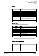
Bit
Information
Notes
7
Off
Excluded
8
Non-default value
Abnormal condition resulting in a reduced safety
9-12
—
Not used
13
Fault
Faulty
14
—
Not used
15
Alarm
Activated / Alarmed
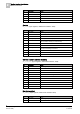
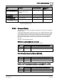
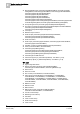
Power Supply
WT_PowerSupply (Input register, default base address: 6600)
Bit
Information
Notes
0 (lsb)
Non-default mode
Default range for possible abnormal mode
1-7
—
Not used
8
Non-default value
Currently not used (foreseen for future extensions)
9
—
Not used
10
Emergency Power
Due to missing or faulty mains supply, the FS20/FS720 is
operating in battery mode.
11-12
—
Not used
13
Fault
Troubles with the power supply: mains or battery failure
11-15
—
Not used
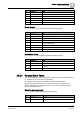
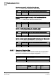
Unidentified Event
WT_Unidentified (Input register, default base address: 8000)
Bit
Information
Notes
0 (lsb)
Non-default mode
Default range for possible abnormal mode
1-7
—
Not used
8
Non-default value
Abnormal condition coming from an object not included in the
configuration
9-15
—
Not used
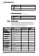
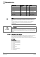
2.2.2.4 Compact Status Tables
The compact tables provide a summarized representation for the following objects:
Detection zones: 4-bit status representation
Detection elements (logical channels): 2-bit status representation
The corresponding data structures, illustrated here below, are packed in the
register areas defined at configuration time. The word input registers contain 4
zones and 8 elements each.
Detection zone (compact)
CT_Zone (Input registers, default base address: 8100)
Bit
Information
Notes
0 (lsb)
-
Not used
1
Off and Test mode
Off and test mode