
User Manual


Modbus Interface Specifications
2
Modbus Data Model
25
Building Technologies
A6V10316242_a_en
CPS Fire Safety
31.05.2019
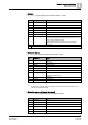
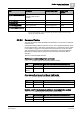
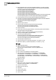
Table
Information
Related object type
Default base
address
BT_CtrlChanModeOff&Test
Control element (control
channel) in test mode or
excluded
Control elements
18000
BT_HWObjAlarm
Hardware object alarm
Hardware components
19000
BT_HWObjFault
Hardware object fault
Hardware components
20000
BT_PowerSupplyFault
Power supply fault
Power supply unit
32000
BT_PowerSupplyEmerPow
er
Power supply emergency power
Power supply battery
33000
1)
If the Channel Delegation option is configured, the Pre-alarm and Alarm events are on the
element level (not the Zone level).
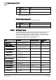
2.2.2.6 Command Tables
The command tables enable the Modbus master/client to issue control commands
to the fire units.
A read/write holding register is foreseen for each of the objects listed below. Given
an initial object state, a data value corresponding to a control action can be written
in the register to trigger the command that is then expected to modify the object
state and therefore cause a corresponding change in the object input registers.
Note that the holding registers store the code of the latest command after its
execution.
The list of command tables includes:
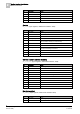
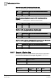
Global panel acknowledgement and reset
CMDT_FC20 (Holding register, default base address 25000)
State
Command (dec)
New state after a successful command execution
Ack required
12
Panel acknowledged
Reset
required
14
Panel reset
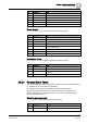
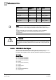
Area manned/unmanned: set day or night mode
CMDT_Area (Holding register, default base address 31000)
State
Command (dec)
New state after a successful command execution
Unmanned
3
Manned (day mode)
Manned
4
Unmanned (night mode)
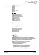
Section on/off: include/exclude all zones belonging to the section
CMDT_Section (Holding register, default base address 30000)
State
Command (dec)
New state after a successful command execution
Off
5
On
On
6
Off