
User Manual


Modbus Interface Specifications
2
Modbus Data Model
37
Building Technologies
A6V10316242_a_en
CPS Fire Safety
31.05.2019
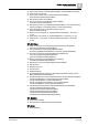
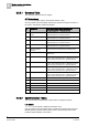
The counter stops being incremented if any of these events occurs:
The communication between the NK823x gateway and the Modbus unit goes
down (this event can be detected and handled by other Modbus units).
The communication between the NK823x gateway and the fire panel goes
down.
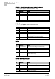
Bit
Information
Notes
0-15
Panel Vitality Counter
Incremented every 250 msec as long as operating properly
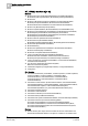
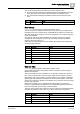
Data Change
DataChange (Input registers, default base address: 1020)
A set of 33 input word registers (525 bits are used) reporting any modifications in
the register area. The complete range of 65536 Modbus registers is covered, with
each flag representing changes in one or more registers in a corresponding group
of 125 word registers.
The first flag, such as the least significant bit of the first change word register,
corresponds with the registers 0 to 124, the second flag corresponds with the
registers 125 to 249, and so on.
Active flags are automatically reset upon reading the registers that changed and
caused the flags activation.
Word / Bit
Information
Notes
0 / 0
Registry 0-124 (00h-7Ch)
Flag 0
0 / 1
Registry 125-249 (7Dh-F9h)
Flag 1
…
Flags 2 to 14 (Word register 0)
0 / 15
Registry 1875-1999 (0753h-07CFh)
Flag 15
…
Flags 16 to 522 (Word registers 1 to 32)
32 / 11
Registry 65375-65499 (FF5F-FFDBh)
Flag 523
32 / 12
Registry 65500-65535 (FFDC-
FFFFh)
Flag 524
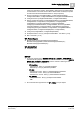
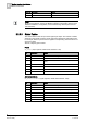
Date and Time
DateTime (Holding registers, default base address: 1060)
Three holding (read/write) word registers used for reading or synchronizing the
NK823x date and time.
The synchronization must be enabled in the configuration settings and results, in
turn, in the synchronization of the fire system (FS20 and then STT20 via FS20).
Alternatively, if the synchronization on these registers is not enabled, the NK823x
gateway gets date and time periodically from the fire system (FS20). In this case,
writing to the registers is disabled, and a Modbus error code 0x04 is returned when
trying a write command.
When synchronization occurs, all registers should be written in sequence to
prevent any possible data interpretation error. The NK823x gateway acquires the
new time stamp when the last of the 3 values is written.
The three 16-bit registers are organized in 6 byte containing 6 hexadecimal values
corresponding with day, month, year, hour, minute, and second respectively.
Word / Bit
Information
Notes
0 / 0-7
Day
1-31 code in hexadecimal, e.g. 1B hex for day 27.
0 / 8-15
Month
1-12 code in hexadecimal
1 / 0-7
Year
10-99 code in hexadecimal
1 / 8-15
Hour
0-23 code in hexadecimal