
User Manual


2
Modbus Interface Specifications
Modbus Data Model
38
Building Technologies
A6V10316242_a_en
CPS Fire Safety
31.05.2019
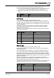
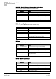
Word / Bit
Information
Notes
2 / 0-7
Minute
0-59 code in hexadecimal
2 / 8-15
Second
0-59 code in hexadecimal
Note: For detailed information about the time synchronization options on the
Modbus host interface, refer to the Modbus interface configuration section of the
NK8237 Installation, Configuration, and Commissioning manual (document no.
A6V10316241).
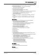
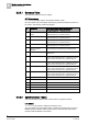
2.2.3.3 Status Tables
The status tables include an input word register per object. The number of tables
depends on the specific systems whose object list is defined at configuration time.
For example, there may be 8 function registers corresponding with 8 functions of a
given fire system.
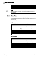
The list of object types includes:
Panel
WT_Panel (Input registers, default base address: 1100)
Bit
Information
Notes
0 (lsb)
Non-default mode
Abnormal mode resulting in a reduced safety
1-7
-
Not used
8
Non-default value
Abnormal condition such as states resulting in a reduced
safety
9-12
-
Not used
13
Fault
14
-
Not used
15
Alarm
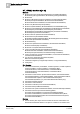
Activation Mode
WT_ActivationMode (Input registers, default base address: 1300)
Bit
Information
Notes
0 (lsb)
Non-default mode
Abnormal mode resulting in a reduced safety
1-7
-
Not used
8
Non-default value
Abnormal condition resulting in a reduced safety
9-11
-
Not used
12
Anomaly
STT20 in mixed mode
13
Fault
STT20 in manual mode
14-15
-
Not used