
User Manual


Modbus Interface Specifications
2
Modbus Data Model
49
Building Technologies
A6V10316242_a_en
CPS Fire Safety
31.05.2019
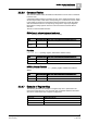
2.2.4 NK823x Gateway Register Map
2.2.4.1 Status Tables
The gateway status tables include two types of input word registers applied to a
number of objects.
NK823x Gateway Points
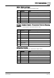
WT_NK8237Point (Input registers, default base address: 8000)
This table is applied to seven objects:
NK823x Status
NK823x Tamper
Clock (NTP connection fault)
Generic Inputs (up to 3 optional signals, which may be used for reporting the
power supply supervision)
Relay Output (optional, reporting a Modbus communication fault)
Therefore, up to seven registers are provided, each one corresponding with one
object.
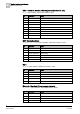
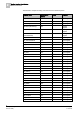
Bit
Information
Notes
0 (lsb)
Non-default mode
Currently note used (foreseen for future extensions).
1-6
-
Not used
7
Tamper disabled
Tamper detection disabled.
Note: this information is only available on the tamper register.
8
Non-default value
Currently note used (foreseen for future extensions).
9
Abnormal
Configuration mismatch between gateway and fire system.
Note: this information is only available on the NK823x status
register.
10-12
Not used
13
Fault
Connection fault.
14
Not used
15
Alarm
Activated / Alarmed / Tamper.
Note: this information is available on the Tamper, Input and
Output registers.
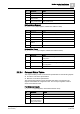
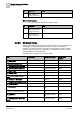
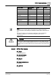
2.2.4.2 NK823x Objects
This section lists the gateway objects and the corresponding types in the NK823x
Modbus data model (refer to the Register Map section [➙ 16]).
WT_NK823xPoint
Application node (NK823x status)
NK823x unit tamper
Digital Input Onboard (power supply supervision or generic inputs)
Digital Output Onboard (Modbus communication fault)
Clock (NTP connection fault)
WT_NK8237Point
Automatic Zone (ZoneAutomaticElem (template 1 or unknown))
Manual FSE Zone (ZoneFseElem)