
User Manual

21
Building Technologies 048_DMS_DF8000_ICC_MP4.20_A6V10081388_a_en.doc
Fire Safety & Security Products 06.2009
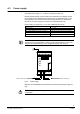
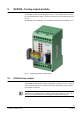
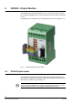
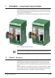
Fig. 15 DF8020 Front panel and external connections 1-16
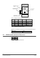
Module Address Switch 1 Switch 2 Switch 3 Notes
0
Off ↓ Off ↓ Off ↓
1
st
module
1
On ↑ Off ↓ Off ↓
2
nd
module
2
Off ↓ On ↑ Off ↓
3
rd
module
3
On ↑ On ↑ Off ↓
4
th
module
4
Off ↓ Off ↓ On ↑
5
th
module
5
On ↑ Off ↓ On ↑
6
th
module
Tab.10. DF8020 Module Address settings
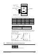
Max Output load (resistive load) 1A / 30 VDC
Relay lifetime 10
5
cycles
Output pulse (pulse activation command
from management station)
16 sec (fixed)
Tab.11. DF8020 max. ratings
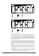
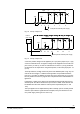
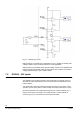
Output contacts 1, 2, 3, 5, 6, and 7 are set as NO by default (outputs 1 and 4 are
provided with terminals for both NO and NC). Internal soldering jumpers can be
used to set NC contacts.
Fig. 16 DF8020 soldering jumper for NO / NC contacts 1-3 and 5-7
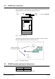
5.2 DF8020 module mechanical dimensions
Width 45 mm
Height 75 mm
Depth 48 mm
Tab.12. DF8020 mechanical dimensions
910111213141516
87654321
1
DF8020
Output
1
2
3
4
5
6
7
8
I²C connector to
I/O modules
LEDs reporting status
of outputs
Dip-switches for
address selection (1...6)
I²C connector to I/O
modules or CPU module
1 2 3
5 6 7
1 2 3
5 6 7
1 2 3
Normally
closed
Normally open
(default)