
User Manual


Configuring control units – Fire
115
Building Technologies
DMS8000 Network, Fire, and Intrusion Connectivity Configuration Guide
Fire Safety & Security Products 06.2009
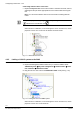
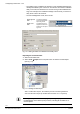
Fig. 114 Selecting the icon to add a FC700A system
A Click this icon to add a FC700A system
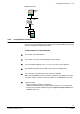
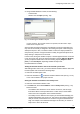
Adding the FC700A control unit to the system node
1. Select the FC700A system node.
2. Select the FG700A (see Fig. 115-A) or the FC700A (see Fig. 115-B) control unit
icon to add a FC700A control unit.
A new node is added to the project structure.
Fig. 115 Adding FC700A units and FG700A gateways
A Click this icon to add a FG700A gateway
B Click this icon to add a FC700A control unit
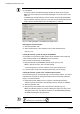
Setting the FC700A Local Address and the Vitality Timer
Set the vitality timer so that the DMS will monitor the FC700A. You set the vitality
timer in the Node tab of the FG700A, and each FC700A.
1. Select the FC700A node.
2. In the Node tab, set the Local Address, the Vitality Timer and the
ACK mode option (see Fig. 93 p. 96). Please note that.
−
The address value should range from 111 to 248 according to the DMS7000
addressing scheme (last digit cannot be 0 or 9), and it should match what is
set in the configuration of the FC700A unit.