
User Manual

Configuring other control units
209
Building Technologies
DMS8000 Network, Fire, and Intrusion Connectivity Configuration Guide
Fire Safety & Security Products 06.2009
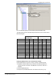
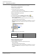
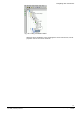
Fig. 190 DMX MUX_MM_IE2, 24 monitored inputs (E2A041MUX card)
The table below shows the interrelationship between the Instance number and the
DMS7000 telegram:
MUX_MM_IE4 /
DMX_MM_OE1
MUX_MM_IE2
Instance number Sector ADF1 ADF2 Sector ADF1 ADF2
1 P (E) E1 01 … 48 P (E) E1 01 … 24
2 P (E) E1 49 … 96 P (E) E1 49 … 72
3 P (E) E2 01 … 48 P (E) E2 01 … 24
4 P (E) E2 49 … 96 P (E) E2 49 … 72
5 P (E) E3 01 … 48 P (E) E3 01 … 24
6 P (E) E3 49 … 96 P (E) E3 49 … 72
7 P (E) E4 01 … 48 P (E) E4 01 … 24
8 P (E) E4 49 … 96 P (E) E4 49 … 72
9 P (E) E5 01 … 48 P (E) E5 01 … 24
10 P (E) E5 49 … 96 P (E) E5 49 … 72
11 P (E) E6 01 … 48 P (E) E6 01 … 24
12 P (E) E6 49 … 96 P (E) E6 49 … 72
Tab.1. Instance number / DMS7000 telegram
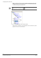
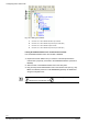
Linking the DMS7000 unit to the Communication network
Link the DMS7000 unit node to the Cerloop, CDI-Net, or NK8000 network.
1. Expand the network folders until you reach the node that represents the
network physically connected to the DMS7000 unit (Cerloop, CDI-Net, or
NK8000).
2. Select the DMS7000 node.
3. Drag and drop the DMS7000 node to the network node (see Fig. 191).