NK8000 MP4.50 NK8222, NK8223, NK8225, NK8231, NK8232, NK8235 Installation Function & Configuration Commissioning Safety Regulations Building Technologies 29.06.
Table of Contents About this document.........................................................................................................5 1 Safety regulations ..............................................................................................8 1.1 Country-specific standards...................................................................................8 1.2 Assembly and installation.....................................................................................8 1.
5.2 5.1.2 NK822x hardware installation .............................................................30 5.1.3 NK823x hardware installation .............................................................37 NE8000 cabinets ................................................................................................41 5.2.1 NE8000 hardware requirements .........................................................41 5.2.2 NE8000 hardware installation .........................................................
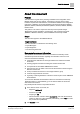
About this document About this document Purpose This document is a guide to the planning, installation and configuration of the NK8000 safety and security network. It includes an overview of the system, hardware requirements and limitations, and detailed installation and configuration instructions. Hardware components detailed in this manual include the NK822x (NK8222, NK8223, NK8225) and NK823x (NK8231, NK8232, NK8235, NK8237) Ethernet Ports.
About this document 3. In the resulting area on the right, click on Contents link to show the list of search results. For more information such as Siemens news and announcements, visit the STEP Web portal at: https://workspace.sbt.siemens.com/content/00001123/default.aspx NOTE: Before beginning work on the system you must have read and understood the Safety Regulations section in this manual.
About this document – Network tunnelling for remote CS6 configuration on NK822x. A6V10062437_a_en 12.2009 Update for NK8000 MP4.20-01: – NK8232 and NK8235 released with some limitations. A6V10062437_a_en 06.2009 Update for NK8000 MP4.20: – NK8232 and NK8235 (announced). – IIS security and Lockdown tool. A6V10062437_a_en 06.2008 Update for NK8000 MP4.15: – New DF8000 I/O module support with improved CMX-DL protocol. A6V10062437_a_en 06.2007 Update for NK8000 MP4.
1 Safety regulations Country-specific standards 1 Safety regulations This section describes the danger levels and the relevant safety regulations applicable to the use of the products described in this manual. Please read the following work instructions as well as the preceding section About this document thoroughly before beginning any work. Danger potential to individuals NK82xx units are powered with low voltage DC.
Safety regulations Disposal and recycling 1.4 1 Disposal and recycling These devices include electrical and electronic components and must not be disposed of as domestic waste. Current local legislation must be observed. The NK82xx units have been manufactured as much as possible from materials that can be recycled or disposed of in a manner that is not environmentally damaging.
2 Introduction NK8000 System Overview 2 Introduction This section provides a description of an NK8000 system and its components. 2.1 NK8000 System Overview The NK8000 family provides LAN/WAN adapter products for a safety and security network, which is based on TCP/IP, BACnet/IP, and Ethernet standards. It works together with Siemens Danger Management Systems (DMS) to manage distributed safety and security units.
Introduction Interactions 2.2 2 Interactions Local interactions Interactions are possible between the subsystems connected to each NK82xx unit and the locally connected I/O modules. Incoming messages can trigger one or more command messages to other subsystems. Thanks to the high reliability of the NK82xx units, these interactions are more secure than reactions and sequences programmed on the management station level.
2 Introduction What has been changed in MP4.50 2.3 What has been changed in MP4.50 Here is the list of modifications included in this version for new functions and improvements. Section Modifications System limits [➙ 13] Up to 4 Modbus clients can now be connected. New system limits. Configuring IP settings via NW8202 [➙ 50] Secure download option now available. Menu "Send Default Configuration File" [➙ 67] Using log files [➙ 65] 2.3.1 Logging on USB device (new section).
System limits NS8210 driver system limits 3 3 System limits The following describes the system limits for the NK82xx units and the corresponding NS82xx drivers for DMS8000 (MM8000 and MK8000) systems. 3.1 NS8210 driver system limits NS8210 Ethernet Port connections (CMSDL/IP and CEI 79-5) Currently, there is a limit of 500 NK82xx units per NS8210. NOTE: Please contact customer support for configurations above 100 NK82xx.
3 System limits NK8222/NK8223/NK8225 system limits 3.3 NK8222/NK8223/NK8225 system limits Network capabilities (upstream towards management system host) Ethernet IEEE 802.3, 10Base-T, half-duplex, no auto-sensing or autonegotiation Single host transport protocols: – CEI 79-5 type A and B (optional FEAL 64-bit encryption) – CMSDL/IP – BACnet/IP (NK8225 only) Multiple hosts (up to four) transport protocols: – CMSDL/IP – BACnet/IP (NK8225 only) DHCP is currently not supported.
System limits NK8231/NK8232/NK8235/NK8237 system limits 3.4 3 NK8231/NK8232/NK8235/NK8237 system limits Network capabilities (upstream towards management system host) 2 Ethernet interfaces IEEE 802.
3 System limits NK8231/NK8232/NK8235/NK8237 system limits LON bus connectivity LON bus connectivity for CS6 Guarto is not supported on NK823x. Interaction capabilities NK8232 and NK8235 provides programmable interaction programs, including single or multiple triggers (incoming events) and single or multiple effects (outgoing control actions). Interactions are only possible between locally connected subsystems.
Structure and functions NK822x hardware 4 4 Structure and functions 4.1 NK822x hardware The NK822x is composed of an electronic board (with optional plug-ins) installed in a compact and robust plastic box. NK822x Ethernet port (NK8223 in this example) 4.1.1 Front panel The front panel houses 9 LED’s. Left Side LED’s The five LED’s on the left side are, from top to bottom: Power (LED green) Power (hardware – controlled).
4 Structure and functions NK822x hardware Right Side LED’s The four LED's on the right side are, from top to bottom: 4.1.2 Name Function Com1 Status Com1 Com2 Status Com2 Com3 Status Com3 Com4 Status Com4 Red: RX Green: TX Internal DIP switches The internal DIP switches enable a download session via FTP using a default IP address. 4.1.3 Internal switch Functions DIP switch 1 Not used.
Structure and functions NK822x hardware Item 4.1.4 4 Description 1 DIP-Switches 2 Reset button 3 JP6: enable LON resistor. 4 Tamper switch 5 JP3: disable tamper or connect to external tamper. Serial interfaces NK8223 / NK8225: although the maximum number of serial lines is 4, they are not always used. There are two serial lines available on the base module and two on an expansion module. NK8222: this model is equipped with two serial lines only available on the base module.
4 Structure and functions NK822x hardware 1 2 3 4 5 6 Back NK822x LN board diagnostic LEDs Item 1 Name Function CD00251 Rev.A boards CD00251 Rev.
Structure and functions NK822x hardware E E D C B A E D D C B A E D D C B A E E D C C B 9 B A A 7 9 9 E E D C C 7 7 9 B B A 6 6 6 6 A 5 5 L 9 7 9 D 1 4 C 0 3 4 5 5 B 8 2 3 4 4 A F 2 3 3 7 9 CD00251 Rev.A boards 6 1 H 8 L 5 2 2 Node 4 0 1 3 F 0 2 6 8 1 H 8 H 5 0 F 4 6 6 8 1 3 5 F 0 2 Subnet 5 H 1 L 8 4 4 0 F 3 3 8 1 2 2 L F 0 8 7 F 7 1 9 0 7 F 4 CD00251 Rev.
4 Structure and functions NK822x hardware 4.1.7 I2C interface: I/O and power supervision This interface allows for a direct support of: Direct digital input/output: – One or two DF8040 (CF9040) input modules – One DF8020 (CF9020) output module Power supply supervision: – One DF8090 power supply supervision module All modules can be installed on the DIN-rail, next to NK822x unit. DF8020 DF8020 is a module providing 8 relay outputs, NO or NC.
Structure and functions NK823x hardware 4 For more information about the DF8000 Input/Output modules, including installation details, see documents DF8000 Datasheet (document no.A6V10081184) and DF8000 ICC (document no.A6V10081388) 4.2 NK823x hardware The NK823x is composed of an electronic board (with optional plug-ins) installed in a compact and robust plastic box.
4 Structure and functions NK823x hardware On: critical/hardware fault. Diagnostics (LED yellow) Internal interface diagnostics: Off: status OK. Blinking (fast): booting operating system after restart. Blinking (1 flash): missing or insufficient license. Blinking (2 flashes): trouble with the I2C bus to I/O modules. Blinking (3 flashes): not used Blinking (4 flashes): trouble with the serial/network interface. Blinking (5 flashes): trouble with DLL or RCLOCK file(s).
Structure and functions 4 NK823x hardware 1 2 X1 X2 X3 3 X101 X102 X103 X104 X105 X115 X111 NK823x internal DIP switch and jumpers (NKM8001 -A1 mainboard) Item Name Description 1 S101 DIP-Switches 2 S1 Reset button 3 S2 Tamper switch 1 2 X1 X2 X3 3 X101 X102 X103 X104 X105 X115 X111 NK823x internal DIP switch and jumpers (NKM8001 -A2 mainboard) 25 Building Technologies Fire Safety & Security Products A6V10062437_a_en 29.06.
4 Structure and functions NK823x hardware Item 4.2.4 Name Description 1 S101 DIP-Switches 2 S1 Reset button 3 S2 Tamper switch Serial interfaces NK8231.2, NK8232.2, NK8235.2 and NK8237.2: these models are equipped with two serial lines available on the NK823x main board. NK8235.4: this model is equipped with 4 serial interfaces (two on the main board and two on an expansion module). COM3 and COM4 do not support the hardwarehandshaking signals for modem control (Rx, TX, and GND only).
Structure and functions NK823x hardware 4 X101 onboard relay output. Pin Signal 1 Common 2 NO 3 NC Circuit X101 2 NO 1 3 4.2.
4 Structure and functions NK823x hardware PW MAINS 1 AC/DC LOW BATT BATT FUSE 2 DF8090 front panel Item Description 1 LEDs. 2 I2C connector to I/O modules. See figure NK823x power connections (see NK823x hardware installation [➙ 37]) for the NK823x power connections using the power supervision module. NOTE: Locally connected DF8000 I/O modules are only supported with NK823x with build state 10 or higher (NKM8001-A2 mainboard).
Structure and functions NK823x hardware 4 Back 1 2 Ethernet connectors Item 4.2.9 Description 1 Ethernet 2 2 Ethernet 1 USB interface The NK823x main board is equipped with a USB interface you can use to log data about network communications on a USB mass storage device (see Network Connectivity Guide, document no.A6V10359485). 29 Building Technologies Fire Safety & Security Products A6V10062437_a_en 29.06.
5 Hardware installation Installation of NK82xx units 5 Hardware installation There are various possible NK8237 installation scenarios. Namely: Installation of NK82xx in existing cabinets. a. DIN-rail mounting (typical) in plastic housing. b. Mounting of the NK82xx board in the control unit housing using card holders and mounting kits. Note that: – The available mounting kits are listed in the NK8000 datasheets.
Hardware installation Installation of NK82xx units 5 4. Connect and install the modules, then connect the I/O points to the modules. For more information about the DF8000 Input/Output modules, including installation details, see documents: DF8000 Datasheet (document no. A6V10081184) DF 8000 ICC (document no A6V10081388) 5. Connect power supply. See Figure Power connections if using a DF8090 power supply supervision module.
5 Hardware installation Installation of NK82xx units Bottom view 1 2 3 4 Serial RS232 interfaces Item Name Description 1 COM 3 — 2 COM 4 — 3 COM 1 In place of CN4 4 COM 2 — NOTE: NK8222 and some NK8223/NK8225 configurations do not include COM3/COM4.
Hardware installation Installation of NK82xx units 5 CN1: Ethernet connector A standard RJ45 connector connects Ethernet. Cat.5 UTP cabling is best suited. Ethernet connections. Pin Assignment 1 TX+ 2 TX– 3 RX+ 4 n.c. 5 n.c. 6 RX– 7 n.c. 8 n.c. CN3: Power supply Power connections. Pin Assignment 1 + PWR 2 Earth 3 – PWR 1 4 — 5 — CN4 (NK822x) / X104 and X105 (NK823x): RS485 connectors RS485 connectors. Pin Assignment 1 + RS485 2 – RS485 COM 1 ...
5 Hardware installation Installation of NK82xx units CN3: LON connection (CS6 Guarto) LON connections. Pin Assignment 1 — 2 — 3 — 4 LON-A 5 LON-B A LON TP/FT-10 network segment can be set up for bus- or free topology. LON repeaters can connect the segments. Up to four LON repeaters (such as NK8020) might be used to extend the size of a LON network. See LON interface [➙ 19] for additional information. LON TP/FT-10 network segment characteristics. Characteristic Bus topology Free topology Max.
Hardware installation 5 Installation of NK82xx units I2C interface 1 2 3 4 SIEMENS Power Vital functions Com 1 Com 2 Com 3 Com 4 Tamper Download Diagnostic PW MAINS AC/DC LOW BATT BATT FUSE DF8090 NK8223 DF8040 12345678 12345678 1 3 2 DF8040 DF8020 12345678 12345678 4 NK822x I2C bus addresses Item Description 1 Address setting (factory setting): address 8. 2 Address setting (factory setting): address 1. 3 Address setting (factory setting): address 2.
5 Hardware installation Installation of NK82xx units NOTE: For more details, see document no. 008725 (CS11 EP7F Planning). NK822x mounting option for CS6 Guarto NK822x mounting option for SI410420 Intrunet 36 Building Technologies Fire Safety & Security Products A6V10062437_a_en 29.06.
Hardware installation Installation of NK82xx units 5.1.3 5 NK823x hardware installation Installation 1. Install the NK82xx unit on the DIN rail. 2. Connect subsystems: – Subsystem lines using the standard RS232 interfaces on COM1 - COM4. Note: Only COM1 and COM2 are available on NK8231 and NK8232. – If used in place of COM1, the RS485 interface is on X104. – If used in place of COM2, the RS485 interface is on X105. 3. If used, connect the power supply supervision module DF8090. 4.
5 Hardware installation Installation of NK82xx units Bottom view 1 2 3 4 Serial RS232 interfaces (bottom view) Item Name Description 1 COM 3 — 2 COM 4 — 3 COM 1 In place of X104. 4 COM 2 In place of X105. NOTE: COM 3 / COM 4 is only available on NK8235.4. Power connections Note the dual power supply input for redundant solutions.
Hardware installation Installation of NK82xx units 5 WARNING There is a risk of explosion if the battery is replaced with an incorrect battery type. Use 27Ah 12V batteries. Dispose of the used battery at a recycling point in accordance with local environmental standards and regulations. X103: Power Supply Power and LON connections.
5 Hardware installation Installation of NK82xx units 3 Input 3 (Power supply fault) 4 Common 5 + Val 6 – Val COM 1 … COM 4: RS232 Connectors RS232 lines are connected to 9pin D-Sub connectors, female type. RS232 connections. Pin Assignment NK822x NK823x COM: 1-2 NK8235.
Hardware installation NE8000 cabinets 5 Installation in Subsystem Housing Without DIN-Rail NK823x can be installed without the plastic box using the specific mounting kits available for CS11/CS440 and SI410. Note that the NKA8011-A1 mounting plate is also needed together with the specific mounting kits. NKA8011-A1 mounting plate 5.2 5.2.
5 Hardware installation NE8000 cabinets 5.2.2 NE8000 hardware installation Cabinet installation The cabinet is typically wall-mounted. A proper support must be provided for the maximum weight (see Technical data on the specific NK8000 datasheet). Four supporting screws or hooks (min. 10 mm) are required. WARNING Supporting wall must not be composed of inflammable material. 360 mm 415 mm Cabinet installation The VAC power supply wires (1.
Hardware installation NE8000 cabinets 5 Input VAC 1.
5 Hardware installation NE8000 cabinets Wiring (1) – Front view of cabinet (arrow indicates cut-out holes) Wiring (2) – Entrance hole indicated by arrow 5.2.2.1 NK8021 modem mounting in an NE8000 cabinet 1. Screw in the modem holder brackets using the holes provided in the back of the cabinet. 2. Slide the modem plate into the brackets. 3. Align the holes in the sides of the modem plate with the clips on the front of the brackets and then press down on the clips to fix the modem in place. 4.
Hardware installation NE8000 cabinets 5 NK8021 modem in NE8000 cabinet 45 Building Technologies Fire Safety & Security Products A6V10062437_a_en 29.06.
6 Software installation NW8202 IP configuration download tool 6 Software installation NK8000 software installation includes the following: Composer and related tools for system configuration. – DMS8000 product setup Additional tools: NW8202 / NW8204 This section lists the hardware and software requirements for the NW8202 and NW8204 tools, and details how to install them. NOTE: The DMS8000 installation CD includes separate set-ups for the NW8202 and NW8204. 6.
Software installation NW8204 maintenance and diagnostic tool 6.2 6 NW8204 maintenance and diagnostic tool The NW8204 is a powerful maintenance and diagnostic tool, which provides functionalities for (but not limited to) the following: Downloading firmware Setting IP addresses Loading default configurations Using available diagnostic files NOTE: Part of the NW8204 tool is available in Composer (limited functionality). For details, see the Network Connectivity Guide (document no.
6 Software installation NW8204 maintenance and diagnostic tool Install Shield Wizard opens. 5. Follow the instructions in the installation wizard. For installing the software on a Composer-only PC, do the following: 1. Logon to computer as Administrator (for details ask network administrator). 2. Insert the Installation CD. 3. Select the NK8000 – Support Tools folder. 4. Select NW8204.exe. Install Shield Wizard opens. 5. Follow the instructions in the installation wizard.
Configuration Configuration checklist 7 7 Configuration After you have installed the Danger Management System (DMS) and Composer, you need to configure the DMS (follow product-specific Installation Function & Configuration Commissioning Guide). Once that is done, you perform the NK8000 configuration procedures to get the NK82xxs communicating with the Danger Management System.
7 Configuration Configuring IP settings via NW8202 7.2 Configuring IP settings via NW8202 This configuration must be performed before the NK82xx can be configured at the client’s site. This procedure details how to send the IP configuration information; that is, the IP address, Subnet mask, and Default address to the NK82xx via the NW8202 Tool. NOTE: This configuration procedure can be performed prior to shipping the NK82xx to the client, or at a later time at the client’s site. 1.
Configuration Configuring IP settings via NW8202 7 8. Click Download. The Download Procedure window is displayed. 9. Follow the instructions displayed. NOTE: Note the different dip-switch depending on the NK82xx model. NW8202 IP configuration download instruction window Back Ethernet connector on NK822x Back Connect Ethernet cables on NK823x 51 Building Technologies Fire Safety & Security Products A6V10062437_a_en 29.06.
7 Configuration Configuring IP settings via NW8202 NOTE: Use a crossed Cat. 5 twisted pair patch cable for direct connection between PC and NK822x. In such direct connections with NK823x, you can use a straight-through cable since these units support automatic crossover. While the download is being performed, the FTP Diagnostic window is displayed with the current status of the download. Once the operation has been performed, a final status notification and instruction window will be displayed.
Testing the configuration Checking the DMS - NK82xx connection(s) 8 8 Testing the configuration We recommend that you test connections during the configuration process so you can more easily narrow down the cause of any problems. This is because you may have problems in run-time where no error message is generated. 8.1 Checking the DMS - NK82xx connection(s) Verify that the NK82xx(s) communicate with the DMS This needs to be done from the host station.
9 Maintenance and diagnostics Kernel update 9 Maintenance and diagnostics 9.1 Kernel update The NK823x Kernel is the main component of the operating system, which acts as a bridge between the application and the hardware level. In certain conditions, it may be necessary to update the NK823x Kernel, following specific instructions of the technical support. In such cases, you can use the NK8000Kernel_Update Setup.msi tool that is available in the NK8000 - Support Tools folder of the DMS8000 CD.
Maintenance and diagnostics SNMP monitoring 9.2 9 SNMP monitoring The NK823x units can support the SNMP protocol (Simple Network Management Protocol) to enable remote stations to monitor the units for conditions that may require administrative attention. Using the SNMPv1 (RFC 1155-1157) on the UDP port 161, the NK823x provides two sets of internal information variables using the community IDs listed here below that enable the access to the MIB (Management Information Base) namespace.
9 Maintenance and diagnostics The NW8204 maintenance and diagnostic tool NW8204.exe Web browser NW8204 tool Server NS8210 NS8210 Web server TCP/IP NK8000 diagnostic tools This section details how to access and use these specialised tools to maintain and troubleshoot an NK8000 network and its components. Both tools have the same NW8204 functionalities. NOTE: Many of the functions detailed in this section are available in Composer.
Maintenance and diagnostics The NW8204 maintenance and diagnostic tool 9.4.1 9 Launching NW8204 from DMS host To access the NW8204 tool, do the following: You need to install the NW8204 maintenance tool (via the installation CD) on the host DMS before proceeding, if it is not already installed. For NW8204 installation instructions, see NW8204 maintenance and diagnostic tool [➙ 47]. 1. Select Start > Programs > NW8204 > NW8204 (executable file).
9 Maintenance and diagnostics The NW8204 maintenance and diagnostic tool NOTE: Inserting an incorrect IP address causes the following window to appear. If you receive this message, select OK and re-type the IP Address. If you want to enter the NK82xx default IP address 192.168.9.41, you can use the menu Set Default IP Address instead of typing it. 3. If connecting to NK823x, enable the checkbox next to Read Product ID. 4. Select Open Connection.
Maintenance and diagnostics The NW8204 maintenance and diagnostic tool 9 3 Local File Browse for a local copy of DIAGNO.LOG or EEPROM.LOG to analyse/troubleshoot a remote NK82xx (admin user only). 4 Set Default IP Address See step 2. 5 Send Default Configuration File See Menu "Send Default Configuration File" [➙ 67]. 6 History log frame — 7 Error log frame — 8 Download/Upload progress status Transferred Bytes, Percent, and Byte/Sec rate.
9 Maintenance and diagnostics The NW8204 maintenance and diagnostic tool 9.4.3 Diagnostic functions Reset NK Allows you to reset an NK82xx from a remote location. NOTE: This function is only available when logged in as user “admin”. Save EEProm on file Stores the content of the EEProm in the file EEProm.LOG on the NK82xx flash disk. Set System Time Sets the RTC (Real Time Clock) of NK82xx to the PC system time. NOTE: This function is only available when logged in as user “admin”.
Maintenance and diagnostics The NW8204 maintenance and diagnostic tool 9 The window can be updated manually by pressing the Refresh button. You can use it to check if status changes are sent correctly from NK82xx (for example from the tamper switch). Read DLL Version Reads all subsystems configured. Displays a dialog box with a list of configured subsystems organised by name, number, and creation date. Read Kernel Version Reads the version of the Linux kernel installed on NK823x .
9 Maintenance and diagnostics The NW8204 maintenance and diagnostic tool Possible port numbers are 3001, 3002, 3003, 3004, and 4000 (CMSDL/IP) or 47808 (BACnet). At that point, the associated field shows the type of information found (e.g. Last IP connected) and you can to use the field arrow controls to show the actual IP address. NOTE: If the IP address shows ‘0.0.0.0’, no PC was connected to that port. Read HW version Reads the NK823x hardware version (NKM8001-A1, NKM8001-A2, …). NOTE: NK823x MP4.
Maintenance and diagnostics The NW8204 maintenance and diagnostic tool 9 Diagnostic file description DIAGNO.LOG This file is always present, and contains detailed technical information about the behaviour of the software application running on the NK82xx. For example, if it wasn’t possible to open an internal queue during the initialisation phase, that message is saved to this file. The information in this file is not meant to be used by filed engineers on site. In case of technical problems, the DIAGNO.
9 Maintenance and diagnostics The NW8204 maintenance and diagnostic tool 23 EV_EEPROM_CPU_CHANGE CPU changed 24 EV_EEPROM_ETH_PNP_UPDAT E Ethernet EEProm update 25 EV_EEPROM_ETH_PNP_ERROR Ethernet EEProm update failed 34 EV_EEPROM_DLL_LOAD_FAILED DLL load failure 35 EV_EEPROM_DLL_EXCLUDED DLL excluded from round-robin schedule 36 EV_EEPROM_DLL_OVERRUN DLL response time over threshold 1 37 EV_EEPROM_DLL_VER_ERR DLL version error 38 EV_EEPROM_DLL_INIT_ERR DLL initialization error 39
Maintenance and diagnostics The NW8204 maintenance and diagnostic tool 9 NOTE: The diagnostic files can be sent to customer support for analysis. Once analysed, you will be instructed what to do to resolve your problem. 9.4.5 Using log files NK823x units can be configured by Composer in order to automatically log data about network communications on a USB mass storage device (see Network Connectivity Guide, document no.A6V10359485).
9 Maintenance and diagnostics The NW8204 maintenance and diagnostic tool Uploading log data NOTE: If the data upload procedure seems to require a too long time to be accomplished, you can abort the procedure by clicking the Abort Log Upload button. NOTE: The log file can be imported as CSV file in a spreadsheet application in order to be analyzed by expert users (Technical Support).
Maintenance and diagnostics The NW8204 maintenance and diagnostic tool 9 NOTE: Resetting the NK823x unit restores the original logging configuration saved in Composer. WARNING Removing the USB key while the logging is enabled (without using the Unmount command, see Diagnostic functions [➙ 60]) may cause the NK823x to restart or block (a manual restart is then needed). Always use the Unmount command before removing the USB memory device! 9.4.
9 Maintenance and diagnostics The NK8000 Web Server tool 9.5 The NK8000 Web Server tool The NK8000 Web Server tool provides an NS8210 diagnostic utility in addition to the NW8204 tool. The NS8210 provides NK82xx branch status information, and also a context command menu for each NK82xx branch upon selection. It communicates to the NK82xxs via TCP/IP using either CMSDL or CEI protocol. To the end user, the NS8210 appears to function in the same way as the NW8204 tool.
Maintenance and diagnostics The NK8000 Web Server tool 9 Adding IIS 3. Select Details. 4. Check the FTP Server box, then select OK. 5. Select Next. NOTE: You may be able to Browse to select where you want to store the utility. 6. Select Finish. If you install IIS after installing MM8000 / MK8000, you must perform the following steps to reset the registry keys: 1. Press Start > Run to open the Run windows. 2. Browse to the folder: > Utilities > Bat 3. Select NK8210ConfigurationTool.
9 Maintenance and diagnostics The NK8000 Web Server tool Note that NK8000 Web Server is not listed in the Server Templates presented by the Lockdown tool wizard. You can however select the generic template Other and then enable the Web Service (HTTP) and File Transfer Service (FTP), the only ones required NK8000 Web Server. For more information refer to Microsoft documentation (e.g.: http://support.microsoft.com/kb/325864).
Maintenance and diagnostics The NK8000 Web Server tool 9 NK8000 Web Server startup window - Changing user NOTE: There are two ways you can log in to the NK8000 Web tool: - Guest user (default): user name = “guest” / password = “guest” (read-only privileges, automatic login). - Administrative user: call customer support for username and password (read/write privileges). Case sensitive – enter letters in lower case only.
9 Maintenance and diagnostics The NK8000 Web Server tool Pop-up command menu for a single NK82xx branch Send commands to a specific NK82xx by selecting the Commands icon and clicking the command in the pop-up menu. The command list includes: – Build Identification: Start a CEI 97-5 identification procedure. – Get Version: Get and display the NK82xx version. – Out scan: Set the NK82xx unit out of scan. After that, the In Scan command will be available.
Maintenance and diagnostics The NK8000 Web Server tool 9 Filtering and searching the NK82xx list The upper frame presents two selection fields to filter and select branches respectively. Filter the NK82xx list by selecting on of the options in the Filter by list and clicking Apply filter. Filtering NK82xx branches Search and mark a specific NK82xx unit by selecting one of the searching options and entering the value to search.
9 Maintenance and diagnostics Correcting communication failures Searching and marking NK82xx branches by name 9.6 9.6.1 Correcting communication failures NK82xx generated a fault If an NK82xx generates a fault, there may be one or more causes. The problem may be in the NK82xx unit, or in the NK82xx connection to the DMS. Check the NK82xx Check power, vital function, and diagnostic state on the respective LED, which is located on the front panel of NK82xx.
Maintenance and diagnostics Correcting communication failures 9.6.2 9 Control unit generated a fault If a control unit generated a fault, the problem may be in the connectivity between one of the control units (or subsystems) and the NK82xx. Check network connections CerCom/LON (CS6 Guarto only) The LON networks are sensitive to improper termination.
9 Maintenance and diagnostics Correcting communication failures 9.6.4 CS6 Guarto generated a fault When adding and configuring a CS6 node, verify that you have the correct Subnet, Node, and Logical address. Ensure that the LON Physical address matches what is physically on the rotary switches of the Guarto LON-adapter board K3I070. NOTE: The LON Physical address: Subnet 01. Node 02 and the BACnet Logical Address 1 are reserved for the NK822x itself and must not be used for the Guarto.
Secure operation requirements 10 10 Secure operation requirements The security of systems requires appropriate planning and proper organizational procedures. Please review the following basic checklist of the issues to consider: Physical Security Access to the room and/or areas where the communication units and control stations are installed should be reserved to authorized personnel, and/or adequate protection should be put in place on the computers to prevent potential attacks or sabotage.
Issued by Siemens Switzerland Ltd Infrastructure & Cities Sector Building Technologies Division International Headquarters Gubelstrasse 22 CH-6301 Zug Tel. +41 41-724 24 24 www.siemens.com/buildingtechnologies Document ID A6V10062437_a_en Edition 29.06.2012 © 2012 Copyright Siemens Switzerland Ltd Technical specifications and availability subject to change without notice.