
User manual

Installation
2-10
SIMATIC 505–2557 Installation and Operation Guide
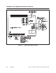
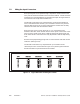
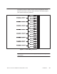
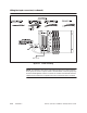
Wiring the Input connectors (continued)
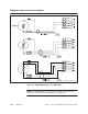
Ground
at One End Only
Figure 2-5 Wiring
Diagram for 2, 3, or 4 W
ir
e R
TD
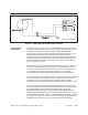
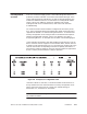
NOTE:
For proper operation, ensure that the SIMA
TIC 505–2557 is not
subjected to large temperature gradients during operation.