Desigo Room Automation Product Range Description Application Guide A6V10866237_en--_b_08 2020-03-17 Building Technologies
Table of Contents 1 Product range overview........................................................................... 9 2 Connecting to the automation level ..................................................... 14 3 Connecting to Desigo CC ...................................................................... 15 4 Applications............................................................................................ 16 5 User roles ..................................................................
12.5.1 HVAC operator panel (upper half) .................................................52 12.5.2 Electric operator panel (lower half) ............................................... 53 12.6 Room operator unit QMX3.P02....................................................................... 54 12.6.1 Electric operator panel (lower half) ............................................... 54 13 Room coordination functions ................................................................ 56 13.
16.7 16.8 16.9 16.10 16.11 16.12 16.13 16.14 16.15 16.16 Valve protection ............................................................................................... 88 Determination of heating/cooling state........................................................ 88 Heating/cooling demand ................................................................................ 88 Preheating ........................................................................................................
18.1 18.2 18.3 18.4 18.5 18.6 18.7 18.8 18.9 18.10 18.11 18.12 18.13 18.14 18.15 18.16 18.17 18.18 18.19 18.20 18.21 18.22 18.23 18.24 18.25 18.26 18.27 18.28 18.29 18.30 18.31 18.32 18.33 18.34 Locked by electric heating coils .................................................................. 127 Start of air volume flow by heating demand .............................................. 127 Water register for 4-pipe system ................................................................
19.8 19.9 19.10 19.11 19.12 19.13 19.14 19.15 19.16 19.17 Start of air volume flow by heating demand .............................................. 160 Actuators......................................................................................................... 160 Valve protection ............................................................................................. 161 Determination of heating/cooling state...................................................... 161 Heating/cooling demand .....
20.31.1 Heat pump...................................................................................... 187 21 21.1 21.2 21.3 21.4 21.5 21.6 21.7 Room pressurization and fume hood control ..................................... 188 Product range overview ................................................................................ 188 Application types ........................................................................................... 192 Room and room segments ....................................
24.4 Automation station for facade control ........................................................ 263 24.5 Automation station for hierarchical grouping of central applications..... 264 24.5.1 Automation station for HVAC supply and demand signals and manual control for lighting and blinds, floor level (Cen-Flr) .... 266 24.5.2 Automation station for emergency controls for HVAC, light, and blinds, floor level (Cen-Flr) .......................................................... 267 24.5.
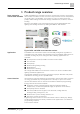
Product range overview 1 1 Product range overview Room automation station DXR1 and DXR2 DXR1 and DXR2 room automation stations are perfectly suited for creating the ideal comfort conditions for the room user. They measure room air temperature, air quality (CO2), and humidity, and control fan coils, air volume flow, heat pumps, chilled ceilings and heated ceilings, chilled beams, radiators, and floor heating. Moreover, the DXR2..
1 Product range overview ● Central operation of operating mode ● Distribution of measured values from the weather station ● Central blinds control Functional extension KNX PL-Link Each DXR2 room automation station has an integrated KNX PL-Link interface. The interface integrates communicating room operator units and field devices. One device on the KNX PL-Link is as easy to engineer and functionally integrate as the fixed inputs and outputs on the DXR2 room automation station.
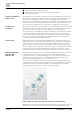
Product range overview Flush mounted room operator units KNX PLLink 1 communications, can acquire, depending on the type, room temperature, humidity, and air quality (CO2). Types are available with or without display and operating elements, Green Leaf or air quality indicators. All commonly used internal flush mounting formats are supported, so that these devices can be combined with virtually any switching program.
1 Product range overview 2 x Light dimming 2 x Blinds This operator panel manually operates 2 KNX PL-Link light outputs and 2 KNX PL-Link blinds outputs, requiring 4 horizontal button pairs. 4 x Light dimming 2 x Blinds ● Switch off + Dim lighting ● Switch on + Make lighting brighter ● Blinds down ● Blinds up This operator panel manually operates 4 KNX PL-Link light outputs and 2 KNX PL-Link blinds outputs. It requires 4 individual buttons and 2 horizontal button pairs.
Product range overview 1 Figure: VAV compact controller (left) and rotary actuator for 6-port control ball valve (right) Light and blinds switch KNX PL-Link The DELTA i-system and DELTA style switch systems communicate with the DXR2 using the bus transceiver module over KNX PL-Link. The button interface UP220/31 integrates conventional buttons to the DXR2 room automation station over the KNX PL-Link.
2 Connecting to the automation level 2 Connecting to the automation level A Desigo PXC00-E.D (or another Desigo PXC…-E.D) is used to integrate the configurable Desigo room automation. The automation station takes over the scheduler system function. Scheduler object in the PXC00-E.D control the room automation central functions and exchanges demand signals with the primary plant. As option, configurable Desigo room automation with DXR2 can also be integrated in any other BACnet system.
Connecting to Desigo CC 3 3 Connecting to Desigo CC Topology The system controller PXC00-E.D is preferred for integrating configurable room automation on the Desigo CC management station. The PXC00-E.
4 Applications 4 Applications Various application types can be used on each DXR2. They contain applications for room conditions, lighting, and shading. It is the I/O mix of the DXR2 automation station that determine characteristics of the application types. Each DXR2 can operate one active and configured application type. Preloaded At least one application type, suitable to the I/O mix is preloaded on each DXR2 automation station. This increases efficiency since there is no download.
Applications Configuration of KNX PL-Link field devices 4 All application types provide a selection of supported field devices. They can be selected and configured. Figure: Example of selecting KNX PL-Link field devices Engineering configured functions and field devices The parameters can be changed on all configured functions and field devices. The system presets all parameters; they can be changed as needed.
5 User roles 5 User roles DXR2 automation stations supports various user roles in the system. A user name and password can be assigned to each user role. Access roles and passwords are required to connect to the DXR2 automation station. We suggest the following user roles as a standard in DXR2.
Web server 6 6 Web server Access via web browser The DXR2 automation station has an integrated web server. Access to this web server is password protected can takes place via the automation station IP address. A web browser is required for access. Online operation and monitoring The DXR2 web server permits online access to all configured BACnet data points and their properties to the applicable DXR2 automation station. The data points and properties can be operated in the web server and/or monitored.
7 Rooms and room segments 7 Rooms and room segments Room Each DXR2 automation station can control one room. One segment also belongs to the room in each DXR2. The DXR2 includes the control function for the room as well as control function for the associated room segment. Room control includes all functions that apply to the entire room including Green Leaf or, for example, room temperature controller.
Rooms and room segments 7 The given room function is once again enabled when dividing up a large room to various smaller rooms and connected to the associated room segment functions. The system ensures that there is only one active room function per room and supports the switching of room segments with the same application types.
7 Rooms and room segments Automatic control logic for HVAC Multisegment applications always ensure full coordination of individual electrical and mechanical installations of jointly used room control in the room segment. All HVAC controllers (e.g. temperature or fresh air) is automatically managed by the system when rooms are combined or separated and interconnected with the correct segments.
Central function with groups 8 8 Central function with groups Central function A central function implements central control functions and coordinated demand and forced signals. A central function acts through a group in the planned rooms or wings. The central function can also collect and compile, via the group, demand signals or state signals from the wings or rooms. Hidden behind the central control functions are system functions such as operator interventions (via BACnet clients, e.g.
8 Central function with groups Grouping functions help structure and centrally control large numbers of different system elements and data. Grouping can take place by organizational, geographic, functional, or cross-discipline criteria. Group cooperation supports data exchange between central control functions and individual system elements. Hierarchical groups A group master can for its part be a group member of a superposed group master.
Alarms System alarms on DXR2 9 9 Alarms The DXR2 has internal alarms. The alarm concept for Desigo room automation distinguishes between system alarms and process alarms. 9.1 System alarms on DXR2 System alarms monitor the reliability of data points or the state of networked devices. This always occurs as a common alarm for the room, the room segment, or central function. This information can be read and displayed via BACnet client, e.g. a management station.
9 Alarms Time response to system and process alarms Binary input Description Name Default value Monitoring binary input Enable event detection 1:No 0:Yes 1:No State that trigger the alarm. Event parameters 0:Active Time delay for alarm Time delay 0 [s] Alarm description text Description Monitoring binary input n Description Name Default value Monitoring analog input Enable event detection 1:No 0:Active 1:Inactive Analog input 0:Yes 1:No Note State that trigger the alarm.
Trends 10 10 Trends Desigo room automation provides a series of trends in each room. Trends are not enabled by default. The following trends can be enabled for each room (through configuration): ● Trend room temperature ● Trend room air quality ● Trend relative room air humidity ● Trend room operating mode ● Trend blinds command The enable and trend type must be configured for each enabled trend.
11 Control function Room operating modes 11 Control function 11.1 Room operating modes The operating states Comfort, Pre-Comfort, Economy, and Protection are available to the application functions on the DXR2 automation station. The room operating modes apply for the entire room and are superposed for the three disciplines HVAC, lighting, and shading. In other words, the response of HVAC, lighting, and blinds applications are taken from it. The response can be configured for each room and each discipline.
Control function 11 Room operating mode determination Temporary Comfort by room operator unit The Comfort button on the QMX3 room operator units can also be used as a temporary comfort function. When configured for temporary presence function, the room user can activate Comfort mode for 120 minutes (configurable) by pressing the button. Pressing the button again will re-trigger the timer for 120 minutes. Control using the scheduler (on PXC00-E.
11 Control function Plant operating mode determination 11.3 Plant operating mode determination The present operating state of the HVAC plant in a room depends on room operating mode, central supply signals, and local influences. Local influences here include window contact or presence detector. In addition to room operating modes Comfort, Pre-Comfort, Economy, and Protection, there is states Night cooling, boost heating, and rapid cooling for the plant operating mode.
Control function 11 Plant operating mode determination Control using window contact Control using a presence detector Heating and cooling output is reduced to a minimum when a window is opened. The DXR2 automation station always switches to Protection operating mode. The window contact is connected directly to the DXR2 digital input.
11 Control function Room controller and setpoints 11.4 Room controller and setpoints The DXR2 applications possess 5 different room controls: ● Temperature control for heating ● Temperature control for cooling ● Air quality control ● Air volume flow tracking control (for positive or negative pressure control in room for VAV) ● Humidity control (for local dehumidification via the cooling coils on fan coils) Enabled controllers communicate with one another.
Control function Room controller and setpoints 11 The room operator unit cannot influence the heating and cooling setpoints for Economy or Protection. Comfort setpoints as seasonal compensation The Comfort setpoints for temperature control in the room is mapped in the central function for seasonal compensation. The central seasonal compensation (setpoint shift based on outside temperature) causes a gradual increase in room temperature as a function of the outside temperature.
11 Control function Room controller and setpoints 11.4.2 Temperature control: Direct or cascading DXR2 applications support two forms of temperature control: Direct temperature control and room supply air cascade. Direct temperature control On direct room temperature control the room controller directly calculates the output signal (0...100%) for the aggregates from the measured room temperature. Room supply air cascade Room supply air cascade quickly achieves the room temperature setpoint.
Control function 11 Room controller and setpoints 11.4.3 Air quality setpoints Each room has 4 different setpoints for air quality: One each for operating modes Comfort, Pre-Comfort, Economy, and Protection. The setpoints can be configured on the DXR2. A setpoint is selected and used for control depending on the actual room operating mode. Setpoint configuration 11.4.4 The air quality setpoints can be configured on the DXR2.
11 Control function Room controller and setpoints 11.4.6 Room controller output signals Room controller output signals The room controllers forward their output signals (0…100%) to all impacted aggregates in all segments of the room. For example, the heat controller, that control room temperature, always forwards its output signal to all enabled aggregates including radiators, ceiling heating, and heating coils.
Control function Room controller and setpoints Fan coil application VAV application Fan-Powered Box Heat pump application A6V10866237_en--_b_08 11 The control sequences for temperature control in a fan coil application can be adapted through the following parameters: Description Name Default value Outside damper cooling sequence DmpOaCSeq 1 Radiated ceiling cooling sequence RcgCSeq 2 Heating/cooling coils cooling sequence HCclCSeq 3 Cooling coil cooling sequence CclCSeq 4 Fan cooling s
11 Control function Room controller and setpoints 11.4.
Control function 11 Room controller and setpoints 11.4.8 Controller operating mode for heating and cooling aggregates based on the plant operating mode For the room operating modes, the controller operating mode can be configured on DXR2 for all heating and cooling aggregates.
11 Control function Room controller and setpoints Controller operating mode 2-position Controller operating mode 2-position controls the output signal based on an hysteresis and delay. Figure: Curve for controller operating mode 2-position Key: 11.4.
Control function Room controller and setpoints 11 The following example illustrate the response of the output for a 4-position controller compared to room temperature.
11 Control function Output signals to the aggregates 11.5 Output signals to the aggregates The room controllers forward their output signal to the aggregate signal converter as 0…100% signal. Each aggregate possess a signal converter that always converts the 0…100% signal to the aggregate's configured output signal. Demand and locking signals are coordinated between the individual controls with the converters to ensure the proper functioning of the application.
Control function Output signals to the aggregates 11.5.1 11 Staged output The stage converter associated with staged aggregates, e.g. a 3-stage ventilator, is always enabled. The threshold values for the stage converter are fixed in DXR2 and cannot be changed. The stages switch based on the room controller in %.
12 Operation in room Output signals to the aggregates 12 Operation in room The configurable Desigo room automation and control system supports QMX3 room operator units for wall mounting. The plug-and-play devices, featuring KNX PL-Link communications, can acquire, depending on the type, the room temperature, humidity, or air quality. Types are available for the various use cases both with and without display and operating elements.
Operation in room 12 Green Leaf 2 x Light dimming 2 x Blinds This operator panel manually operates 2 KNX PL-Link light outputs and 2 KNX PL-Link blinds outputs, requiring 4 horizontal button pairs. 4 x Light dimming 2 x Blinds ● Switch off + Dim lighting ● Switch on + Make lighting brighter ● Blinds down ● Blinds up This operator panel manually operates 4 KNX PL-Link light outputs and 2 KNX PL-Link blinds outputs. It requires 4 individual buttons and 2 horizontal button pairs.
12 Operation in room Room operator unit QMX3.P34 12.2 Room operator unit QMX3.P34 Figure: Room operator unit QMX3.P34 Function The room unit QMX3.P34 is used in rooms ● to acquire the room temperature ● to operate Comfort and HVAC functions The room operator unit communicates with the DXR2 room automation station via the KNX PL-Link bus. A segmented LCD display displays the HVAC states in the room.
Operation in room Room operator unit QMX3.P74 Operation 12 The following operating elements can configured to be available to the room user: Green Leaf operation Room setpoint. - Operation Room setpoint. + Operation Fan stage operation Select display Operation of presence control or temporary Comfort extension 12.3 Room operator unit QMX3.P74 Figure: Room operator unit QMX3.P74 Function A6V10866237_en--_b_08 The room unit QMX3.
12 Operation in room Room operator unit QMX3.P74 Display and arrangement of the buttons The top half of the device consists of one LCD display and capacitive buttons to operate HVAC room functions. The HVAC function selection and operation occurs on buttons 1 through 8; the Green Leaf (green/red lead) is located in the upper right-hand corner on button 5. Figure: Configurable displays on the QMX3.
Operation in room Room operator unit QMX3.P36 12 12.4 Room operator unit QMX3.P36 Figure: Room operator unit QMX3.P36 Function The room unit QMX3.P36 is used in the rooms ● to acquire the room temperature ● to operate Comfort and HVAC functions The room operator unit communicates with the DXR2 room automation station via the KNX PL-Link bus. HVAC states are displayed on one LCD display on a page. Various layouts can be selected on the Desigo room automation system for the QMX3.P36.
12 Operation in room Room operator unit QMX3.P36 12.4.
Operation in room 12 Room operator unit QMX3.P36 12.4.3 Layouts for VAV applications The following layouts are available in the configurable Desigo room automation station for VAV applications.
12 Operation in room Room operator unit QMX3.P37 12.5 Room operator unit QMX3.P37 Figure: Room operator unit QMX3.P37 Function The room unit QMX3.P37 is used in rooms ● to acquire the room temperature ● to operate Comfort and HVAC functions ● to operate lighting and blinds applications The room operator unit communicates with the DXR2 room automation station via the KNX PL-Link bus. A segmented LCD display displays the HVAC states in the room.
Operation in room 12 Room operator unit QMX3.P37 ● ● ● ● ● Present setpoint for room temperature relative or absolute in °C Present fan stage Present operating mode for room Display of present displayed data (temperature, humidity, or air quality) Present room occupancy The following operating elements can configured to be available to the room user: Operation Green Leaf operation Room setpoint. - Operation Room setpoint. + Operation Fan stage operation Select display 12.5.
12 Operation in room Room operator unit QMX3.P02 12.6 Room operator unit QMX3.P02 Figure: Room operator unit QMX3.P02 Function The room unit QMX3.P02 is used in rooms ● to acquire the room temperature ● to operate lighting and blinds applications The room operator unit communicates with the DXR2 room automation station via the KNX PL-Link bus. 12.6.1 Electric operator panel (lower half) The lower half of the device consists of one window for a designation sign.
Operation in room Room operator unit QMX3.P02 Templates for labeling A6V10866237_en--_b_08 12 The electrical operator panel uses labels. The labels are inserted from below into the window for the electric operator panel on the QMX3.P02. A template is available to create labels at www.siemens.
13 Room coordination functions Room operator unit QMX3.P02 13 Room coordination functions Comprehensive, configurable applications for room automation are included in the delivery for Desigo. Desigo room automation is based on proven application functions per VDI 3813 as well as energy efficiency class A per DIN EN 15232.
Room coordination functions 13 Room functions: Room coordination (Cont.
13 Room coordination functions Room functions: Room coordination Each discipline has its own rules for determining the influence of energy efficiency that is evaluated in the room coordination function. The criteria for evaluating energy efficiency are: ● The maximum tolerance to manually shift the room temperature setpoint can be configured. Description Name Default value Maximum tolerance of room temperature setpoint shift TolMaxSpTRShft 2 [K] ● Fan speed: No configuration.
Room coordination functions 13 Room functions: Room coordination Room control by switching the operating mode Trigger signals indicate switch to energy efficiency or Comfort The room operating mode can automatically control the various applications for HVAC, lighting, or shading. Two trigger signals are available in each room. They are sent to all disciplines on a configured change to room operating mode occurs. The two triggers are "Energy efficiency condition" and "Comfort condition".
13 Room coordination functions Room functions: Room coordination Example Reactions to the trigger can be configured for the specific discipline. The following table provides an overview on a possible configuration.
Room coordination functions 13 Room functions: Room coordination Impact of the trigger on HVAC A manually adjusted setpoint for HVAC applications can be reset using the trigger for "Energy efficiency condition". Control is reset to automatic. The trigger acts on both the temperature setpoint as well as the setpoint for the fan stage. The application can also recognize whether the change to the room operating mode from an automatic function or was the result of a manual operation.
13 Room coordination functions Room functions: Room coordination Impact of the trigger on Light For lighting applications, lighting can be switched on, off, or reset to automatic using the triggers "Energy efficiency condition" and "Comfort condition". The application can also recognize whether the change to the room operating mode from an automatic function or was the result of a manual operation. It can also be considered during configuration.
Radiator application 14 Hot water radiator application 14 Radiator application 14.1 Hot water radiator application All DXR2 application types include a hot water radiator application. As a rule, each DXR2 can control 2 hot water radiators via Triac or analog outputs. Hot water radiators, the controller operating mode modulating or 2-point can be configured.
14 Radiator application Hot water radiator application Actuators The DRX2 automation station controls radiator valves via Triac or analog outputs, regardless of available I/Os. 3-position actuators, thermal pulse width modulation (PWM) actuators, PWM actuators with return spring can be connected to the Triac outputs. A maximum of 1 thermal valve can be connected to each Triac on the DXR2 automation station with AC 230 V power. PWM actuators with spring return are not supported.
Radiator application 14 Electric radiator application 14.2 Electric radiator application All DXR2 application types include an electric radiator application. As a rule, each DXR2 can control 2 electric radiators via Triac or analog outputs. For electric hot water radiators, the controller operating mode modulating or 2point can be configured.
14 Radiator application Electric radiator application Y Output signal TR Room temperature SpH Effective heating setpoint YH1 1-stage YH Electric radiator Figure: Example of radiator application Actuators The DRX2 automation station controls electric radiator valves via Triac or analog outputs, regardless of available I/Os. Single-stage and modulating electric radiators are supported.
Radiator application 14 Determination of heating/cooling state Downdraft compensation The downdraft compensation functions slows down sinking cold air current at large window surfaces and prevents in this manner a cold wall effect on large, cold surfaces. The function activates the radiator if the outside temperature drops below a configured value by increasing the minimum radiator control to a higher value. A linear reset function implements the downdraft compensation.
14 Radiator application Preheating Demand correction by collected valve positions Valve positions in the various rooms correct the demand setpoint in the central function based on the number of valves between a value of 70...100%. Description Name Default value Setpoint correction, if 100% of all consumers are within 70…100%. SpCorrTFlHi 5 [K] Setpoint correction, if 0% of all consumers are within 70…100%. SpCorrTFlLo -5 [K] 14.
Radiator application Presence control 14 14.10 Presence control The HVAC application can also be controlled by presence through the use of a presence detector. The HVAC application can be configured for each room to react to presence for each room and regardless of the room operating mode.
15 Radiant/chilled ceiling application 2-pipe chilled ceiling 15 Radiant/chilled ceiling application All DXR2 application types include a ceiling heating/chilled ceiling application. As a rule, each DXR2 can control 2 ceiling heating/chilled ceilings via Triac or analog outputs. For ceiling heating/chilled ceilings, the controller operating mode modulating or 2-point can be configured.
Radiant/chilled ceiling application 15 2-pipe heated/chilled ceiling with changeover system 15.
15 Radiant/chilled ceiling application 4-pipe ceiling heating/chilled ceiling with changeover valves 15.
Radiant/chilled ceiling application 4-pipe heated/chilled ceiling with 6-port valve 15 15.
15 Radiant/chilled ceiling application 4-pipe ceiling heating/chilled ceiling with 6-port valve (PL-Link) Parameter settings Description Name Default value Chilled ceiling valve position X1C X1CcgVlvPos 0 [%] Chilled ceiling valve position Y1C Y1CcgVlvPos 50 [%] Chilled ceiling valve position X2C X2CcgVlvPos 100 [%] Chilled ceiling valve position Y2C Y2CcgVlvPos 0 [%] Ceiling heating valve position X1H X1HcgVlvPos 0 [%] Ceiling heating valve position Y1H Y1HcgVlvPos 50 [%] Ceiling he
Radiant/chilled ceiling application 4-pipe ceiling heating/chilled ceiling with 6-port valve (PL-Link) 15 Sequences Y Control signal/rotational angle X Valve opening Y2C Cooling open X2C Cooling valve open Y1C Cooling begins X1C Cooling valve closed Y1H Heating begins X1H Heating valve closed Y2H Heating open X2H Heating valve open YN Valve closed. XN Valve closed.
15 Radiant/chilled ceiling application 2-pipe ceiling heating 15.6 2-pipe ceiling heating Plant diagram Figure: Example for a heated ceiling application 2-pipe system Key: DXR2… Room automation station R1 Room operator unit Rcg Heated ceiling valve D1 Presence CdnMon Condensation monitor D2 Window contact Y Output signal TR Room temperature SpH Effective heating setpoint SpC Effective cooling setpoint YH Heating valve Sequences Figure: Modulating heating sequence 15.
Radiant/chilled ceiling application 15 Valve protection 15.8 Valve protection Valve actuators are operated from time to time to prevent them from seizing after long periods of inactivity (e.g. heating valve during the summer). The valve actuator is controlled to lose as little heating energy as possible. The central function for the hot water supply chain performs the valve protection function and can be changed in the parameters as needed.
15 Radiant/chilled ceiling application Preheating 15.11 Preheating The central functions can trigger the preheating function to heat up a room at end of the night setback period as quickly as possible to the Pre-Comfort setpoint. This impacts the plant operating mode of the application. 15.12 Emergency mode The setpoint for protection ensures that room temperatures do not change below or above a critical limit. 15.
Radiant/chilled ceiling application Dew point temperature monitoring 15 15.17 Dew point temperature monitoring As a supplement to the condensation monitor, the primary chilled water temperature is compared against the present dew point temperature in the room. The chilled beam valve is closed if the chilled water temperature drops below the dew point temperature at a configurable difference.
15 Radiant/chilled ceiling application Presence control 15.18 Presence control The HVAC application can also be controlled by presence through the use of a presence detector. The HVAC application can be configured for each room to react to presence for each room and regardless of the room operating mode.
Radiant/chilled ceiling application Application examples 15 15.19 Application examples These are the descriptions of HIT applications on http://hit.sbt.siemens.com. Visit the Siemens Download Center www.siemens.com/bt/download for the latest application configurations. 15.19.
16 Ceiling heating/chilled ceiling application 2-pipe chilled beams 16 Ceiling heating/chilled ceiling application All DXR2 application types include a passive heated/chilled beam application. As a rule, each DXR2 can control 2 passive heated/chilled beams via Triac or analog outputs.
Ceiling heating/chilled ceiling application 16 2-pipe heated/chilled beam with changeover system 16.
16 Ceiling heating/chilled ceiling application 4-pipe heated/chilled beams with changeover valves 16.
Ceiling heating/chilled ceiling application 4-pipe heated-chilled beams with 6-port valve 16 16.
16 Ceiling heating/chilled ceiling application 4-pipe heated/chilled beam with 6-port valve (PL-Link) Parameter settings Description Name Default value Chilled beam valve position X1C X1CcgVlvPos 0 [%] Chilled beam valve position Y1C Y1CcgVlvPos 50 [%] Chilled beam valve position X2C X2CcgVlvPos 100 [%] Chilled beam valve position Y2C Y2CcgVlvPos 0 [%] Heated beam valve position X1H X1HcgVlvPos 0 [%] Heated beam valve position Y1H Y1HcgVlvPos 50 [%] Heated beam valve position X2H X2
Ceiling heating/chilled ceiling application Actuators 16 Sequences Y Control signal/rotational angle X Valve opening Y2C Cooling open X2C Cooling valve open Y1C Cooling begins X1C Cooling valve closed Y1H Heating begins X1H Heating valve closed Y2H Heating open X2H Heating valve open YN Valve closed. XN Valve closed.
16 Ceiling heating/chilled ceiling application Valve protection 16.7 Valve protection Valve actuators are operated from time to time to prevent them from seizing after long periods of inactivity (e.g. heating valve during the summer). The valve actuator is controlled to lose as little heating energy as possible. The central function for the hot water supply chain performs the valve protection function and can be changed in the parameters as needed.
Ceiling heating/chilled ceiling application 16 Preheating 16.10 Preheating The central functions can trigger the preheating function to heat up a room at end of the night setback period as quickly as possible to the Pre-Comfort setpoint. This impacts the plant operating mode of the application. 16.11 Emergency mode The setpoint for protection ensures that room temperatures do not change below or above a critical limit. 16.
16 Ceiling heating/chilled ceiling application Dew point temperature monitoring 16.16 Dew point temperature monitoring As a supplement to the condensation monitor, the primary chilled water temperature is compared against the present dew point temperature in the room. The chilled beam valve is closed if the chilled water temperature drops below the dew point temperature at a configurable difference.
Ceiling heating/chilled ceiling application Presence control 16 16.17 Presence control The HVAC application can also be controlled by presence through the use of a presence detector. The HVAC application can be configured for each room to react to presence for each room and regardless of the room operating mode.
17 Fan coil application Serial or parallel control strategy 17 Fan coil application The fan coil application can be configured with a fan coil application type. Each fan coil application type can also combine a heated/chilled ceiling (beam) or radiator application. The image below provides an overview of the fan coil application type with all possible HVAC components that can be configured for a fan coil application. The configuration enabled the applicable (required) aggregate on the DXR2.
Fan coil application 17 Serial or parallel control strategy Serial Y Output signal TR Room temperature SpH Effective heating setpoint SpC Effective cooling setpoint YH Heating valve YC Cooling valve FanSpMax H Max. fan speed heating FanSpMaxC Max. fan speed cooling FanSpMinH Min. fan speed heating FanSpMinC Min.
17 Fan coil application Air volume flow in the dead zone The control strategy can be configured in the application using the following parameters for the cooling sequence and heating sequence. Description Name Default value Fan operation for cooling FanOp 1:Parallel FanOp 1:Parallel 0:Serial 1:Parallel Fan operation for heating 0:Serial 1:Parallel 17.2 Air volume flow in the dead zone The fan coil application configures a minimum supply air flow in the temperature control dead zone.
Fan coil application 17 Control of staged fan 17.3 Control of staged fan Fan coil applications in the DXR2 include one to three-stage automatic fan control. The fan stages are switched on or off with potential free relay contacts.
17 Fan coil application Control of staged fan Return air sensor The fan must be switched on if room temperature measurement is made using a return air sensor in the fan coil system, to correctly acquire the actual room temperature. A minimum air volume is enabled in the dead zone by default for the operating mode Comfort on the DXR2. The parameter cannot be changed when using a return air sensor to measure room temperature.
Fan coil application 17 Control of modulating fan 17.4 Control of modulating fan The DXR2 fan coil applications can automatically control modulating fans (DC 0…10 V). In addition, the fan can be enabled or locked with a potential free relay contact.
17 Fan coil application Water register for 4-pipe system 17.
Fan coil application 17 Water register 2-pipe system with changeover 17.
17 Fan coil application Water register for 4-pipe system with changeover valves 17.
Fan coil application Water register 4-pipe system with 6-port valve 17 17.
17 Fan coil application Water register 4-pipe system with 6-port valve (PL-Link) Figure: Modulating heating and cooling sequence with 6-port valve positions Parameter settings Description Name Default value Cooling coil valve position X1C X1CclVlvPos 0 [%] Cooling coil valve position Y1C Y1CclVlvPos 50 [%] Cooling coil valve position X2C X2CclVlvPos 100 [%] Cooling coil valve position Y2C Y2CclVlvPos 0 [%] Heating coil valve position X1H X1HclVlvPos 0 [%] Heating coil valve position Y1H
Fan coil application Water register 4-pipe system with 6-port valve (PL-Link) 17 Sequences Y Control signal/rotational angle X Valve opening Y2C Cooling open X2C Cooling valve open Y1C Cooling begins X1C Cooling valve closed Y1H Heating begins X1H Heating valve closed Y2H Heating open X2H Heating valve open YN Valve closed. XN Valve closed.
17 Fan coil application Water register 2-pipe system, cooling only 17.
Fan coil application Water register 2-pipe system, heating only 17 17.11 Water register 2-pipe system, heating only Plant diagram Figure: 2-pipe system fan coil applications, heating only Key: DXR2… Room automation station R1 Room operator unit Q1 Fan D1 Presence YH Hot water heating coils D2 Window contact Y Output signal TR Room temperature SpH Effective heating setpoint SpC Effective cooling setpoint YH Heating valve Sequences Figure: Modulating heating sequence 17.
17 Fan coil application Valve protection 17.13 Valve protection Valve actuators are operated from time to time to prevent them from seizing after long periods of inactivity (e.g. heating valve during the summer). The valve actuator is controlled to lose as little heating energy as possible. The central function for the hot water supply chain performs the valve protection function and can be changed in the parameters as needed.
Fan coil application Preheating 17 17.16 Preheating The central functions can trigger the preheating function to heat up a room at end of the night setback period as quickly as possible to the Pre-Comfort setpoint. This impacts the plant operating mode of the application. 17.17 Emergency mode The setpoint for protection ensures that room temperatures do not change below or above a critical limit. 17.18 Night cooling The plant operating mode cools a room using cooling outside air.
17 Fan coil application Centrally override valves 17.22 Centrally override valves Central functions permit the central override of all valve in the supply group. The following parameters can be used. Description Name Default value Enable valve position override EnVlvPosOvrr 0:No VlvPosOvrr 100 [%] 0:No 1:Yes Valve position override 17.23 Electric heating coil One electric heating coil can be configured for fan coil applications.
Fan coil application Electric heating coil 17 Sequences Y Output signal TR Room temperature YH1 1-stage SpH Effective heating setpoint YH Electric heating coil Figure: 1-stage electric heating coils Y Output signal TR Room temperature YH1 1-stage SpH Effective heating setpoint YH2 2-stage YH Electric heating coil Figure: 2-stage electric heating coils Y Output signal TR Room temperature YH Electric heating coil SpH Effective heating setpoint Figure: Modulating electric hea
17 Fan coil application Electric heating coil Safety thermostat A binary overtemperature (open contact) protection can be connected on the DXR2 for all versions of the electric heating coil application. The application switches off the electric heating coils at device protection priority if overtemperature protection is enabled.
Fan coil application Electric reheater 17 17.24 Electric reheater DXR2 applications permit control of electric heating coils, in addition to control of water heating valves and/or heating/chilled water valves. They are then operated as reheaters and only enabled if the water heating valve is fully open.
17 Fan coil application Electric reheater Y Output signal TR Room temperature YH1 1-stage electric reheater SpH Effective heating setpoint YH2 2-stage electric reheater YH Hot water heating coils Figure: 2-stage electric reheater Y Output signal TR Room temperature YR Modulating electric heating coils SpH Effective heating setpoint YH Hot water heating coils Figure: Modulating electric reheater Actuators Electric heating coils, controlled via an analog output on the DXR2, can recei
Fan coil application Active chilled beam 2-pipe system 17 17.
17 Fan coil application Active chilled beam 2-pipe system HysTDiffDw Hysteresis minimum difference pChw dew point temperature/chilled water temperature TDiffDwpC hwMin Minimum difference dew point temperature/chilled water temperature TChwPm TDwp Dew point temperature (calculated) Chilled water temperature Figure: Dew point temperature monitoring parameters Dew point temperature monitoring must be enabled.
Fan coil application Room supply air cascade 17 17.26 Room supply air cascade Room supply air cascade quickly achieves the room temperature setpoint. The room controller calculates a setpoint from the room temperature as measured at the air outlet of the air system. The temperature can be limited to prevent the inflow of unpleasantly cool or warm air into the room.
17 Fan coil application Air quality control 17.27 Air quality control The fan coil unit application can be used for air quality control. It requires an outside air damper capable of supplying the room with fresh air and an air quality sensor in the room. The application automatically enabled air quality control as soon as an air quality sensor and an outside damper is configured. Air quality setpoints can be configured separately for each room operating mode.
Fan coil application Outside air damper control 17 17.29 Outside air damper control The outside air damper primary supplies the room with fresh outside air. It can also be used for take advantage of cooler outside air to cool the room. The outside air damper is only opened if the fan is running. This can be based on a cooling request, dehumidification request, or fresh air request.
17 Fan coil application Presence control 17.30 Presence control The HVAC application can also be controlled by presence through the use of a presence detector. The HVAC application can be configured for each room to react to presence for each room and regardless of the room operating mode.
Fan coil application Application examples 17 17.31 Application examples These are the descriptions of HIT applications on http://hit.sbt.siemens.com. Visit the Siemens Download Center www.siemens.com/bt/download for the latest application configurations. 17.31.
18 VAV application Serial or parallel control strategy 18 VAV application The VAV application can be configured using a VAV application type. Each VAV application type can also combine a radiant/chilled ceiling (beam) or radiator application. The image below provides an overview of the VAV application type with all possible HVAC components that can be configured for a VAV application. The configuration enabled the applicable (required) aggregate on the DXR2.
VAV application Serial or parallel control strategy 18 Serial Y Output signal TR Room temperature SpH Effective heating setpoint SpC Effective cooling setpoint YH Heating valve YC Cooling valve VavSuAirFl MaxH VAV maximum air volume flow heating VavSuAirFl MaxC VAV maximum air volume flow cooling VavSuAirFl MinH VAV minimum air volume flow heating VavSuAirFl MinC VAV minimum air volume flow cooling OfsVavSttC Offset for VAV start cooling OfsVavSttH Offset for VAV start heating VAV v
18 VAV application Air volume flow in the dead zone The control strategy can be configured in the application using the following parameters for heating sequence. Description Name Default value Operating variables volume flow system for cooling VavOp 1:Parallel VavOp 1:Parallel 0:Serial 1:Parallel Operating variables volume flow system for heating 0:Serial 1:Parallel 18.
VAV application Air volume flow in the dead zone 18 Sequence with modulating heating valve Y Output signal TR Room temperature SpH Effective heating setpoint SpC Effective cooling setpoint YH Heating valve YC Cooling valve VavSuAirFl MaxH Maximum air volume flow heating VavSuAirFl MaxC Maximum air volume flow cooling VavSuAirFl MinH Minimum air volume flow heating VavSuAirFl MinC Minimum air volume flow cooling VAV volume flow Figure: Serial control sequence for a VAV application wit
18 VAV application Volume flow setpoints heating/cooling 18.3 Volume flow setpoints heating/cooling The volume flow setpoints for heating or cooling sequence can be defined independent of one another. The values are not interdependent.
VAV application Air volume control 18 18.4 Air volume control All explanation of volume flow control ignore air aftertreatment. In order words, the supply air sequences start directly at the room temperature setpoints and not only after air aftertreatment has reached maximum. Temperature control Temperature control works with the actual room temperature setpoints for the actual operating mode and calculates a set volume flow that moves between the minimum and maximum setpoints.
18 VAV application Parallel supply air VAV or extract air VAV 18.4.1 External volume air flow control A differential pressure sensor is typically connected to the VAV actuator for an application with external volume flow control. Which in turns also implements volume flow control. In this case, the application in the DXR2 controls only the room temperature and forwards the setpoint for volume flow control to the VAV actuator.
VAV application Return air sensor 18 18.8 Return air sensor The volume air flow must be available if room temperature measurement is made using a return air sensor in the VAV system, to correctly acquire the actual room temperature. A minimum air volume is enabled in the dead zone by default for the operating mode Comfort on the DXR2. The parameter cannot be changed when using a return air sensor to measure room temperature.
18 VAV application Water register for 4-pipe system 18.
VAV application Water register 2-pipe system with changeover 18 18.
18 VAV application Water register for 4-pipe system with changeover valves 18.
VAV application Water register 4-pipe system with 6-port valve 18 18.
18 VAV application Water register 4-pipe system with 6-port valve (PL-Link) Parameter settings Description Name Default value Cooling coil valve position X1C X1CclVlvPos 0 [%] Cooling coil valve position Y1C Y1CclVlvPos 50 [%] Cooling coil valve position X2C X2CclVlvPos 100 [%] Cooling coil valve position Y2C Y2CclVlvPos 0 [%] Heating coil valve position X1H X1HclVlvPos 0 [%] Heating coil valve position Y1H Y1HclVlvPos 50 [%] Heating coil valve position X2H X2HclVlvPos 100 [%] Hea
VAV application Water register 4-pipe system with 6-port valve (PL-Link) 18 Sequences Y Control signal/rotational angle X Valve opening Y2C Cooling open X2C Cooling valve open Y1C Cooling begins X1C Cooling valve closed Y1H Heating begins X1H Heating valve closed Y2H Heating open X2H Heating valve open YN Valve closed. XN Valve closed.
18 VAV application Water register 2-pipe system, cooling only 18.
VAV application Water register 2-pipe system, heating only 18 18.17 Water register 2-pipe system, heating only Plant diagram Figure: 2-pipe system VAV applications, heating only Key: DXR2… Room automation station R1 Room operator unit YS Supply air VAV D1 Presence YH Hot water heating coils D2 Window contact Y Output signal TR Room temperature SpH Effective heating setpoint SpC Effective cooling setpoint YH Heating valve Sequences Figure: Modulating heating sequence 18.
18 VAV application Valve protection 18.19 Valve protection Valve actuators are operated from time to time to prevent them from seizing after long periods of inactivity (e.g. heating valve during the summer). The valve actuator is controlled to lose as little heating energy as possible. The central function for the hot water supply chain performs the valve protection function and can be changed in the parameters as needed.
VAV application Preheating 18 18.22 Preheating The central functions can trigger the preheating function to heat up a room at end of the night setback period as quickly as possible to the Pre-Comfort setpoint. This impacts the plant operating mode of the application. 18.23 Emergency mode The setpoint for protection ensures that room temperatures do not change below or above a critical limit. 18.24 Reset setpoint The central function can reset a local change to a setpoint on the room operator unit.
18 VAV application Electric heating coil 18.27 Electric heating coil One electric heating coil can be configured for VAV applications. The DRX2 automation station controls electric heating coils via Triac or analog outputs, regardless of available I/Os. Single-stage, 2-stage, 3-stage, and modulating electric heating coils are supported.
VAV application Electric heating coil Y Output signal TR Room temperature YH1 1 stage SpH Effective heating setpoint YH2 2nd stage YH Electric heating coil 18 Figure: 2-stage electric heating coils Y Output signal TR Room temperature YH1 1 stage SpH Effective heating setpoint YH2 2nd stage YH Electric heating coil YH3 3-stage Figure: 3-stage electric heating coils Y Output signal TR Room temperature YH Electric heating coil SpH Effective heating setpoint Figure: Modulat
18 VAV application Electric heating coil Safety thermostat A binary overtemperature (open contact) protection can be connected on the DXR2 for all versions of the electric heating coil application. The application switches off the electric heating coils at device protection priority if overtemperature protection is enabled.
VAV application Electric reheater 18 18.28 Electric reheater DXR2 applications permit control of electric heating coils, in addition to control of water heating valves and/or heating/chilled water valves. They are then operated as reheaters and only enabled if the water heating valve is fully open.
18 VAV application Electric reheater Y Output signal TR Room temperature YH1 1-stage electric reheater SpH Effective heating setpoint YH2 2-stage electric reheater YH Hot water heating coils Figure: 2-stage electric reheater Y Output signal TR Room temperature YH1 1-stage electric reheater SpH Effective heating setpoint YH2 2-stage electric reheater YH Hot water heating coils YH3 3-stage electric reheater Figure: 3-stage electric reheater Y Output signal TR Room temperature
VAV application Electric reheater Safety thermostat 18 A binary overtemperature (open contact) protection can be connected on the DXR2 for all versions of the electric reheater application. The application switches off the electric reheater at device protection priority if overtemperature protection is enabled.
18 VAV application Active chilled beam 2-pipe system 18.
VAV application Night cooling 18 HysTDiffDw Hysteresis minimum difference pChw dew point temperature/chilled water temperature TDiffDwpC hwMin Minimum difference dew point temperature/chilled water temperature TChwPm TDwp Dew point temperature (calculated) Chilled water temperature Figure: Dew point temperature monitoring parameters Dew point temperature monitoring must be enabled. Description Name Default value Enable dew point temperature EnTDwp 0:No 0:No 1:Yes 18.
18 VAV application Presence control 18.31 Presence control The HVAC application can also be controlled by presence through the use of a presence detector. The HVAC application can be configured for each room to react to presence for each room and regardless of the room operating mode.
VAV application Dynamic calibration 18 Description Name Default value Supply air VAV calibration command VavSuBalCmd 0:Ready Supply air VAV balancing state VavSuBalSta 1:Initial Supply air VAV balancing operating mode VavSuBalMod 0: Maximum cooling Supply air flow hood VavSuAirFlHood 100 [m3/h] Supply air VAV recorded balancing operating mode VavSuBalModRec 1: Maximum cooling Supply air VAV recorded air flow hood VavSuAflHodRec 0 [m3/h] Supply air VAV recorded flow coefficient VavSuF
18 VAV application Application examples 18.34 Application examples These are the descriptions of HIT applications on http://hit.sbt.siemens.com. Visit the Siemens Download Center www.siemens.com/bt/download for the latest application configurations. 18.34.
Fan-Powered Box Application examples 19 19 Fan-Powered Box The fan powered box (a fan-supported VAV box) with two controlled air flows. The primary air is controlled with an air damper; the fan is speed controlled. The fan can be physically installed at two different locations: The serial fan and the parallel fan.
19 Fan-Powered Box Application examples Change from parallel to serial fan powered box The fan position must be configured in the application. The monitoring signal of the fan in the VAV is switched on and off: Description Name Default value Enable monitor fan state EnMonFanSta 0:No 0:No (Parallel mode) 1:Yes (Serial mode) The serial fan powered box transports the overall volume flow In a serial FPB application, the supply air can be mixed from return and primary air (cooling).
Fan-Powered Box Application examples 19 An application with serial fan must transfer the fan state to the VAV controller so that the VAV supplies only fresh air if the fan is also operating. This ensures that no fresh air enters the room via the return air duct. The following image is a diagram of the various locking and monitoring signals of a serial fan powered box applications.
19 Fan-Powered Box Application examples Serial fan powered box control sequences The serial fan powered box control sequences are explained using the example with an auxiliary heating register. The associated setting parameters are explained in the following table that lists the preset values.
Fan-Powered Box Application examples Parameter settings The parallel fan powered box transports the recirculating air portion 19 Description Name Default value Supply air VAV maximum air volume flow for cooling VavSuAirFlMaxC 100 [m3/h] Supply air VAV minimum air volume flow for cooling VavSuAirFlMinC 50 [m3/h] Supply air VAV minimum air flow for ventilation VavSuAflMinVnt 0 [m3/h] Fan start speed at the fan powered VAV box FanSttSpdFpb 50 [%] Fan end speed at the fan powered VAV box Fan
19 Fan-Powered Box Application examples The non-return damper ensures on an application with parallel fans, that no fresh air can enter the room via the return air duct. The fan receives demand signals from the VAV box and the auxiliary heating register. The following image is a diagram of various locking and monitoring signals of a serial fan powered box application.
Fan-Powered Box Application examples Serial fan powered box control sequences 19 The serial fan powered box control sequences are explained using the example with an auxiliary heating register. The associated setting parameters are explained in the following table that lists the preset values.
19 Fan-Powered Box Serial or parallel control strategy for the fan Parameter settings Description Name Default value Supply air VAV maximum air volume flow for cooling VavSuAirFlMaxC 100 [m3/h] Supply air VAV minimum air volume flow for cooling VavSuAirFlMinC 50 [m3/h] Supply air VAV minimum air flow for ventilation VavSuAflMinVnt 0 [m3/h] Fan start speed at the fan powered VAV box FanSttSpdFpb 50 [%] Fan end speed at the fan powered VAV box FanEndSpdFpb 100 [%] Maximum fan speed heatin
Fan-Powered Box Serial or parallel control strategy for the fan 19 Parallel Y Output signal TR Room temperature SpH Effective heating setpoint SpC Effective cooling setpoint YH Heating valve YC Cooling valve FanEndSpd PrlH Fan end speed for parallel heating FanEndSpd PrlC Fan end speed for parallel cooling FanSpMinH Min. fan speed heating FanSpMinC Min.
19 Fan-Powered Box Air volume flow in the dead zone 19.2 Air volume flow in the dead zone The fan powered box application configures a minimum supply air flow in the temperature control dead zone. The function can be configured individually for all room operating mode. Description Name Default value Minimum supply air Comfort CmfCnf 4:Minimum ventilation & demandcontrolled ventilation Minimum supply air for Pre-Comfort.
Fan-Powered Box Outputs 19.3.1 19 Description Name Default value Supply air VAV maximum air flow for ventilation VavSuAflMaxVnt 100 [m3/h] 27.78 [l/s] Supply air VAV minimum air flow for ventilation VavSuAflMinVnt 0 [m3/h] 0.
19 Fan-Powered Box Return air sensor 19.6 Return air sensor The volume air flow must be available if room temperature measurement is made using a return air sensor in the FPB system, to correctly acquire the actual room temperature. A minimum air volume is enabled in the dead zone by default for the operating mode Comfort on the DXR2. The parameter cannot be changed when using a return air sensor to measure room temperature.
Fan-Powered Box Valve protection 19 19.10 Valve protection Valve actuators are operated from time to time to prevent them from seizing after long periods of inactivity (e.g. heating valve during the summer). The valve actuator is controlled to lose as little heating energy as possible. The central function for the hot water supply chain performs the valve protection function and can be changed in the parameters as needed.
19 Fan-Powered Box Preheating 19.13 Preheating The central functions can trigger the preheating function to heat up a room at end of the night setback period as quickly as possible to the Pre-Comfort setpoint. This impacts the plant operating mode of the application. 19.14 Emergency mode The setpoint for protection ensures that room temperatures do not change below or above a critical limit. 19.15 Reset setpoint The central function can reset a local change to a setpoint on the room operator unit.
Fan-Powered Box Electric reheater 19 19.18 Electric reheater Electric heating coils, controlled via an analog output on the DXR2, can receive an enable via a relay or Triac on the DXR2. Safety thermostat A binary overtemperature (open contact) protection can be connected on the DXR2 for all versions of the electric reheater application. The application switches off the electric reheater at device protection priority if overtemperature protection is enabled.
19 Fan-Powered Box Presence control 19.20 Presence control The HVAC application can also be controlled by presence through the use of a presence detector. The HVAC application can be configured for each room to react to presence for each room and regardless of the room operating mode.
Heat pump application Serial or parallel control strategy 20 20 Heat pump application The heat pump application can be configured using a heat pump application type. Each heat pump application type can also combine a ceiling heating/chilled ceiling (beam) or radiator application. The image below provides an overview of the heat pump application type with all possible HVAC components that can be configured for a heat pump application.
20 Heat pump application Serial or parallel control strategy Serial Y Output signal heat pump TR Room temperature SpH Effective heating setpoint SpC Effective cooling setpoint YH Heat pump heating YC Heat pump cooling FanSpMax H Max. fan speed heating FanSpMaxC Max. fan speed cooling FanSpMinH Min. fan speed heating FanSpMinC Min.
Heat pump application Air volume flow in the dead zone 20 The control strategy can be configured in the application using the following parameters for the cooling sequence and heating sequence. Description Name Default value Fan operation for cooling FanOp 1:Parallel FanOp 1:Parallel 0:Serial 1:Parallel Fan operation for heating 0:Serial 1:Parallel 20.2 Air volume flow in the dead zone The heat pump application configures a minimum supply air flow in the temperature control dead zone.
20 Heat pump application Control of staged fan 20.3 Control of staged fan Heat pump applications in the DXR2 include one to two-stage automatic fan control. The fan stages are switched on or off with potential free relay contacts.
Heat pump application Control of modulating fan 20 Return air sensor The fan must be switched on if room temperature measurement is made using a return air sensor in the heat pump system, to correctly acquire the actual room temperature. A minimum air volume is enabled in the dead zone by default for the operating mode Comfort on the DXR2. The parameter cannot be changed when using a return air sensor to measure room temperature.
20 Heat pump application Heat pump control Switch-off delay The switch off of a fan is delayed for a specific period on applications that have electric heating coils/reheaters. This cools down the electric heating coils/reheater with circulating air. The switch-on/switch-off time can be configured.
Heat pump application Heat pump control Availability heating 20 Heat pump availability for heating can be configured. Description Name Default value Control mode manual CtlModMan 1:Automatic 1:Automatic 2:Heating 3:Cooling Configuration: 1:Automatic or 2:Heating For efficient heating, you can configure heating based on outside temperature as a supplement to availability.
20 Heat pump application Heat pump control Reversing valve mode On heat pump versions with reversing valve, the position is based on configuration by heat pump operating type. Description Name Default value Reversing valve activated for RvrVlvActv 1:Cooling 0:Heating 1:Cooling The reversing valve is always inactive on device operating mode "Off".
Heat pump application Speed-controlled heat pump with reversing valve control 20 20.
20 Heat pump application 1-stage heat pump with reversing valve control 20.
Heat pump application 2-stage heat pump with reversing valve control 20 20.
20 Heat pump application 2-stage heat pump with reversing valve control and hot gas reheater 20.
Heat pump application 2-stage heat pump with internal reversing valve control 20 20.
20 Heat pump application 2-stage heat pump with internal reversing valve control and hot gas reheater 20.
Heat pump application Actuators 20 20.12 Actuators The DRX2 automation station controls heating/cooling valves via Triac and analog outputs, regardless of available I/Os. 3-position actuators, thermal pulse width modulation (PWM) actuators, PWM actuators with return spring can be connected to the Triac outputs. A maximum of 1 thermal valve can be connected to each Triac on the DXR2 automation station with AC 230 V power.
20 Heat pump application Source demand Demand correction by collected valve positions Valve positions in the various rooms correct the demand setpoint in the central function based on the number of valves between a value of 70...100%. Description Name Default value Setpoint correction, if 100% of all consumers are within 70…100%. SpCorrTFlHi 5 [K] Setpoint correction, if 0% of all consumers are within 70…100%. SpCorrTFlLo -5 [K] 20.
Heat pump application Free cooling 20 20.20 Free cooling The function free cooling to take advantage of cooling generated without effort to cool the rooms to a room temperature setpoint. Dew point compensation is still available for the chilled water temperature setpoint dependent on active dew point detector via the grouping function. This supply chain is continued accordingly, in other words chilled water generation (chillers, refrigeration machines, etc.) are also controlled based on demand. 20.
20 Heat pump application Electric reheater 20.25 Electric reheater The DXR2 applications also permit electric heating coil control in addition to heat pump control. They are then operated as reheaters and only enabled if the heat pump positioning signal is fully open.
Heat pump application Electric reheater Y Output signal heat pump TR Room temperature YH1 1-stage electric reheater SpH Effective heating setpoint YH2 2-stage electric reheater YH Heat pump heating 20 Figure: 2-stage electric reheater Y Output signal heat pump TR Room temperature YR Modulating electric heating coils SpH Effective heating setpoint YH Heat pump heating Figure: Modulating electric reheater Actuators Electric heating coils, controlled via an analog output on the DXR2,
20 Heat pump application Room supply air cascade 20.26 Room supply air cascade The heat pump application does not support the room-supply air cascade. 20.27 Air quality control The heat pump application can be used for air quality control. It requires an outside air damper capable of supplying the room with fresh air and an air quality sensor in the room. The application automatically enabled air quality control as soon as an air quality sensor and an outside damper is configured.
Heat pump application Outside air damper control Setpoints 20 Dehumidification setpoints can be configured separately for each room operating mode. Room temperature based availability Description Name Default value Relative room air humidity setpoint for Comfort SpHuRelRCmf 60 % r.h. Relative room air humidity setpoint for Pre-Comfort SpHuRelRPcf 60 % r.h. Relative room air humidity setpoint for Economy SpHuRelREco 70 % r.h.
20 Heat pump application Outside air damper control Outside temperaturedependent limitation of outside air damper Economizer The characteristic curve for the outside air damper can be limited by the outside temperature. The value can be adapted regardless of internal room load.
Heat pump application Presence control 20 20.30 Presence control The HVAC application can also be controlled by presence through the use of a presence detector. The HVAC application can be configured for each room to react to presence for each room and regardless of the room operating mode.
21 Room pressurization and fume hood control Product range overview 21 Room pressurization and fume hood control 21.1 Product range overview Critical Environment Technology (CET) is a range of reliable air volume flow controllers and supplementary components for the secure, precise and fast measurement, control and monitoring of air volume flows and room pressures in buildings. CET can be easily integrated into building automation systems.
Room pressurization and fume hood control Product range overview Airflow pressure sensor 21 The airflow pressure sensor (APS) is used to measure airflow for room pressurization and fume hood control applications. Figure: APS DXA.S04P1 Figure: APS DXA.S04P1 with IP54 Cover Differential pressure sensor The differential pressure sensor acquires differential, over- and under-pressure of air and nonaggressive gases if a high degree of measuring accuracy and quality is required.
21 Room pressurization and fume hood control Product range overview Flow sensor The flow sensor is suited for accurate and long-term stable recording of the air face velocity of fume hoods with horizontal and vertical sliding front doors. Figure: QVE3001 Cable sash sensor The cable sash sensor is a peripheral device to acquire the sash position of a laboratory fume hood for Siemens laboratory fume hood controllers.
Room pressurization and fume hood control Product range overview Fume hood operating display panels 21 The Operating Display Panel (QMX3.P87) is the interface between the fume hood operator and the control system. It includes a custom-designed package for visual and audible indication of fume hood operating conditions and pushbuttons for emergency mode operation, alarm silence and user-defined auxiliary buttons. The panel is mounted on the wall or fume hood in an easily accessible location.
21 Room pressurization and fume hood control Application types Fast running actuators for air dampers Electronic actuator for 2-position, 3-position, or modulating control, nominal torque 6 Nm, at 2 s running time, self-centering shaft adapter, range mechanically adjustable between 0...90°, prewired with 0.9 m long standard connection cables. Figure: GAP191.1E 21.2 Application types The DXR2.17C… automation station can be flexibly configured, depending on available inputs and outputs.
Room pressurization and fume hood control Alarms 21 Combination of DXR2.E17… DXR2 DXR2 1 Room pressurization Room pressurization 2 Room pressurization Fume hood 3 Room pressurization with thermal power Room pressurization with thermal power 4 Room pressurization with thermal power Fume hood 5 Chilled ceiling and/or radiator application 21.4 Alarms The controller is equipped with ventilation and pressurization alarms.
21 Room pressurization and fume hood control Trends 21.
Room pressurization and fume hood control Pressurized room, temperature control 21 21.7 Pressurized room, temperature control The pressurized room application can be configured using a pressurized room application type. Each application type can also combine a radiant/chilled ceiling or radiator application. The image below provides an overview of the application type with all possible components that can be configured for a pressurized room application.
21 Room pressurization and fume hood control Pressurized room, temperature control ● Coordination of airflow demands for heating, cooling, and ventilation ● Airflow monitoring and alarm values ● Multiple segment support (A segment can include any of the following: supply terminal / extract terminal / supply + extract pair / independent exhaust terminal - fume hood).
Room pressurization and fume hood control Pressurized room, temperature control 21.7.2 21 Ventilation control Ventilation in pressurized rooms can be defined as the rate of airflow through a room to remove and dilute air contaminants. The application sets supply and extract airflow rates to satisfy ventilation requirements. In a positive pressure room the ventilation rate equals supply flow. In a negative room, it equals extract flow.
21 Room pressurization and fume hood control Pressurized room, temperature control Air quality control for minimum ventilation and demand-controlled ventilation DCV The application can be used for air quality control. The room must have an air quality sensor. The application automatically enables air quality control as soon as an air quality sensor is configured. Air quality setpoints can be configured or disabled separately for each room operating mode.
Room pressurization and fume hood control Pressurized room, temperature control 21.7.3 21 Temperature control Temperature control works with the actual room temperature setpoints for the actual operating mode and calculates a set volume flow that moves between the minimum and maximum setpoints. The minimum and maximum air volume flows for a VAV actuator can be configured for each actuator.
21 Room pressurization and fume hood control Pressurized room, temperature control 21.7.4 Air flow control The pressurized room operates a damper, using closed loop control to drive the measured flow to an airflow setpoint that it calculates based on demand signals received for heating, cooling and ventilation. It can control airflow with a settling time of 1 to 2 seconds when applied with the right peripheral devices. It can also be set up for slower operation.
Room pressurization and fume hood control Pressurized room, temperature control 21 Type of airflow Normal use Other possible use Comfort ventilation (RVntMinCmf) RVntMinCmf represents the ventilation rate for the room, not a specific terminal. It may be set to comply with building codes that specify the rate expected / needed when occupants are present (Comfort mode). Might be set according to industry standards for contamination control, or to a client’s institutional standards.
21 Room pressurization and fume hood control Pressurized room, temperature control 21.7.6 Presence control The HVAC application can also be controlled by presence through the use of a presence detector. The HVAC application can be configured for each room to react to the presence signal for each room according to the room operating mode. The application is programmed to respond to presence and absence of occupants in the room. Occupancy includes scheduled and unscheduled use of the room.
Room pressurization and fume hood control Pressurized room, temperature control Supply calibration Description Object Default value Supply air VAV balancing state ▶ Indicates the state of progress of the balancing process for this VAV box. It is written by the controller in response to the user-entered balance command. It persists through a power cycle.
21 Room pressurization and fume hood control Pressurized room, temperature control Exhaust calibration Description Object Type Default value Extract air VAV balancing state ▶ Indicates the state of progress of the balancing process for this VAV box. It is written by the controller in response to the user-entered balance command. It persists through a power cycle. VavExBalSta MCnfVal 1:Initial VavExBalMod MCnfVal 1:Maximum ventilation ACnfVal 0.050 [m2] 0.540 [ft2] ACnfVal 0.
Room pressurization and fume hood control Pressurized room, advanced temperature control 21 21.8 Pressurized room, advanced temperature control The pressurized room with thermal power application is a separate application type. Each application type can also combine a radiant/chilled ceiling or radiator application. The image below provides an overview of the application type with all possible components that can be configured for a pressurized room with thermal power application.
21 Room pressurization and fume hood control Pressurized room, advanced temperature control 21.8.1 Temperature control Room temperature control loop When fume hoods open and close in a VAV laboratory, the resulting changes in supply air flow can disrupt the room temperature. The thermal power sequence is designed to reduce that disruption by calculating and applying a compensating change in the supply air temperature.
Room pressurization and fume hood control Fume hood 21 21.9 Fume hood The fume hood application type handles a fume hood or other laboratory exhaust equipment. It functions independently, but coordinates with a pressurized room control application. The diagram below shows the components and devices that may be configured for use in a fume hood application.
21 Room pressurization and fume hood control Fume hood Description Parameter Switch delay after emergency to emergency setpoint SwiDlySpEmg ▶ If a time value other than 0 is used, then during an emergency purge the fume hood exhaust damper opens to 100% for that amount of time, after which the damper will go to the emergency purge setpoint value in the fume hood exhaust air setpoint AF (FhSpEhxx).
Room pressurization and fume hood control Fume hood 21 and activation of any special operating modes should be based on documented safety procedures for the laboratory. Fume hood Occupancy schedule source – Specifies whether the fume hood responds to its own occupancy schedule or to one for the room. Emergency Flow – In many laboratories, work procedures for handling a spill or other problem in the hood is to close the sash and press the button to call for more air flow.
21 Room pressurization and fume hood control Fume hood Check low sash for low air volume flow – Defines whether the system checks sash position upon a schedule change from occupied to unoccupied. If set to Inactive, the fume hood occupancy is allowed to go to unoccupied regardless of sash position / face area. If set to Active, sash must be lower than the unoccupied alert area or unoccupied alert position before fume hood occupancy can change to unoccupied.
Room pressurization and fume hood control Fume hood 21 The fume hood minimum and maximum airflow provided signals are collected by the room. Variables distributed from room: ● Occupancy ● Fume hood exhaust air flow request from room Exhaust setpoint determination A6V10866237_en--_b_08 The exhaust airflow request from the room will only change the exhaust airflow setpoint when the exhaust setpoint selection is set to auto.
21 Room pressurization and fume hood control Fume hood 21.9.4 Fume hood and ODP interaction The fume hood controller communicates with a hood user through the Operating Display Panel (ODP). The ODPs are networked PL-Link devices. The primary purpose of the ODP is to indicate to the user that the hood is or is not drawing the proper air flow rate. The Fume Hood Flow Alarm state is the data used to indicate sufficient flow.
Room pressurization and fume hood control Fume hood 21 Description Parameter Default value Value to display DspyValue 2:Face velocity 1:Blank 2:Face velocity 3:Exhaust air volume flow 4:Exhaust level 5:Differential air pressure ▶ Alarms will still be displayed at the ODP if set to Blank. Switch-on delay for sash opening alert DlyOnSashAlrt ▶ The length of time after FhSashOpnAlrt turns on before the buzzer will start to beep.
21 Room pressurization and fume hood control Fume hood 21.9.5 Stabilizing jet The stabilizing jet feature is used to monitor and control a fume hood stabilizing jet fan. The status of the stabilizing jet fan is shared with other functions to determine exhaust volume setpoints and generate alarms. The stabilizing jet fan is turned on and off based on fume hood sash position and, fume exhaust air volume flow.
Lighting applications Manual switching or dimmed light 22 22 Lighting applications 22.1 Manual switching or dimmed light The application controls local switching and dimming of lighting in the room. It is optimized for short response times between pushing the button and the response by the lighting actuator.
22 Lighting applications Manual switching or dimmed light Prewarning during switch off Each lighting application has a prewarning function. When enabled, the prewarning function does not immediately turn off lighting when the push button is manually pushed. The light blinks in advance for a defined period. The room user can permanently turn on the light again by pressing the button during the prewarning function.
Lighting applications Stairwell lighting 22 22.2 Stairwell lighting The application provides scheduled switch off of lighting. Lighting is switched on manually. After the overshoot time, it is automatically switched off. This function is often used in stairwells and hallways. It is optimized for short response times between pushing the button and the response by the lighting actuator.
22 Lighting applications Stairwell lighting Prewarning during switch off Each lighting application has a prewarning function. When enabled, the prewarning function does not immediately turn off lighting when the push button is manually pushed. The light blinks in advance for a defined period. The room user can permanently turn on the light again by pressing the button during the prewarning function.
Lighting applications Presence-dependent lighting control 22 Operating hours counter manually reset the counter if exchanging luminaires. You can reset the counter via central operation or on the DXR2 web server. Control of state LED Description Name Default value Operating hours Oph 00:00:00 [hh:mm:ss] The DXR2 can control KNX PL-Link push buttons or room operator units with integrated LED state displays.
22 Lighting applications Presence-dependent lighting control Symbol Description Movement detected by the presence detector. Each movement restarts the delay off presence detector (DlyOffPscDet).
Lighting applications Presence-dependent lighting control Burn-in function Prewarning during switch off 22 Each lighting application function possesses a burn-in function for newly installed fluorescent lights that must be burned in. This ensures that the lights achieve their maximum brightness and life expectancy: ● T5 fluorescent lamps require a burn-in time of 100 hours. ● T8 fluorescent lamps require a burn-in time of 20 hours.
22 Lighting applications Presence-dependent lighting control Control of state LED The DXR2 can control KNX PL-Link push buttons or room operator units with integrated LED state displays. The following state displays can be configured: ● Always off: State LEDs are always switched off on push buttons/room operator unit. ● Lighting on: The state LEDs for the push buttons (switch off/darker) are switched on if the lights are switched on.
Lighting applications Control for daylight based lighting and dusk/dawn switching 22 22.4 Control for daylight based lighting and dusk/dawn switching The application automatically turns off lighting if sufficient daylight is measured in the room and turns it back on for too little daylight. It requires a brightness sensor in the room. The automatic function for turning off the lights can also be locked or enabled. The application can also be used to implement dawn/dusk switching.
22 Lighting applications Control for daylight based lighting and dusk/dawn switching Burn-in function Prewarning during switch off Each lighting application function possesses a burn-in function for newly installed fluorescent lights that must be burned in. This ensures that the lights achieve their maximum brightness and life expectancy: ● T5 fluorescent lamps require a burn-in time of 100 hours. ● T8 fluorescent lamps require a burn-in time of 20 hours.
Lighting applications Constant lighting control with one light group in the room Control of state LED 22 The DXR2 can control KNX PL-Link push buttons or room operator units with integrated LED state displays. The following state displays can be configured: ● Always off: State LEDs are always switched off on push buttons/room operator unit. ● Lighting on: The state LEDs for the push buttons (switch off/darker) are switched on if the lights are switched on.
22 Lighting applications Constant lighting control with one light group in the room When adding presence detectors, lighting is controlled based on daylight and occupancy.
Lighting applications Constant lighting control with one light group in the room Burn-in function Prewarning during switch off 22 Each lighting application function possesses a burn-in function for newly installed fluorescent lights that must be burned in. This ensures that the lights achieve their maximum brightness and life expectancy: ● T5 fluorescent lamps require a burn-in time of 100 hours. ● T8 fluorescent lamps require a burn-in time of 20 hours.
22 Lighting applications Constant lighting control with multiple lighting groups in the room Control of state LED The DXR2 can control KNX PL-Link push buttons or room operator units with integrated LED state displays. The following state displays can be configured: ● Always off: State LEDs are always switched off on push buttons/room operator unit. ● Lighting on: The state LEDs for the push buttons (switch off/darker) are switched on if the lights are switched on.
Lighting applications Constant lighting control with multiple lighting groups in the room 22 Multiple lighting groups control in the room: Influence of daylight and artificial light The parameters luminance, correction factor daylight, and correction factor artificial light must be determined by the corresponding brightness measurement in the room and saved to the automation station to ensure daylight-dependent lighting in the room is operating properly.
22 Lighting applications Constant lighting control with multiple lighting groups in the room Burn-in function Prewarning during switch off Each lighting application function possesses a burn-in function for newly installed fluorescent lights that must be burned in. This ensures that the lights achieve their maximum brightness and life expectancy: ● T5 fluorescent lamps require a burn-in time of 100 hours. ● T8 fluorescent lamps require a burn-in time of 20 hours.
Lighting applications Operating strategy for light Control of state LED 22 The DXR2 can control KNX PL-Link push buttons or room operator units with integrated LED state displays. The following state displays can be configured: ● Always off: State LEDs are always switched off on push buttons/room operator unit. ● Lighting on: The state LEDs for the push buttons (switch off/darker) are switched on if the lights are switched on.
22 Lighting applications Operating strategy for light The reduced control for the corresponding operating mode refers to dimmable lighting in the room. Moreover, the reduction to light output does not include manual control of lighting using operator buttons in the room. A room occupant is always able to control the full illuminance.
Lighting applications Operating strategy for light Burn-in function Prewarning during switch off 22 Each lighting application function possesses a burn-in function for newly installed fluorescent lights that must be burned in. This ensures that the lights achieve their maximum brightness and life expectancy: ● T5 fluorescent lamps require a burn-in time of 100 hours. ● T8 fluorescent lamps require a burn-in time of 20 hours. Refer to manufacturer data on fluorescent lights for more detailed information.
22 Lighting applications Operating strategy for light Control of state LED The DXR2 can control KNX PL-Link push buttons or room operator units with integrated LED state displays. The following state displays can be configured: ● Always off: State LEDs are always switched off on push buttons/room operator unit. ● Lighting on: The state LEDs for the push buttons (switch off/darker) are switched on if the lights are switched on.
Blinds applications Local blinds operations 23 23 Blinds applications 23.1 Local blinds operations This application control local operation of shading in the room. It is optimized for short response times between pushing the button and the response by the lighting actuator.
23 Blinds applications Local blinds operations Protection functions Safety of persons Blinds are opened during a fire to allow people to exit through a window or help emergency responders access the facility. Collision protection Collision protection prevents blinds from closing if a window or door is opened to the outside. Wind protection The protection function ensures that all blinds are commanded to a safe position during strong winds.
Blinds applications Operating strategy for blinds 23 23.2 Operating strategy for blinds Desigo room automation has various room operating modes available to efficiently control shading. The system can efficiently control the room depending on the selected room operating mode. This generally occurs during periods of absence, at night, during holidays, when spaces are not occupied. Optimum room shading must satisfy both energy and comfort-related demands.
23 Blinds applications Operating strategy for blinds Figure: Overview of shading functions 238 | 275 A6V10866237_en--_b_08
Central applications Operating strategy for blinds 24 24 Central applications Central functions The configurable DXR2 room automation provides the following central functions. The functions are used to coordinate supply and demand signals for the entire building or large sections thereof between the rooms and generation plants.
24 Central applications Automation station for HVAC supply and demand signals and manual control for lighting and blinds ● 1 x group for emergency control of facades with 4 facade segments each (3 of which can be delayed) ● 1 x group for protection function of facades with 4 facade segments each (3 of which can be delayed) ● 1 x group for service function of facades with 4 facade segments each (3 of which can be delayed) ● 1 x group for emergency control of all luminaires Sensor placement Connect all sen
Central applications Automation station for HVAC supply and demand signals and manual control for lighting and blinds 24 PAS Automation station for supply plant AS Room automation station BI Digital signals for room operating mode CAS Central automation station for emergency control KNX PLLink KNX PL-Link pushbuttons for central switching/dimming of luminaires and control of facades Figure: Plant diagram for HVAC supply/demand signal automation station 24.1.
24 Central applications Automation station for HVAC supply and demand signals and manual control for lighting and blinds Delay function on large facades Each of the central commands for the room operating mode can be delayed in the building using three additional groups. It is used primarily in buildings with larger facades if control influences act on facades for a change to the room operating mode. The delay can be configured.
Central applications Automation station for HVAC supply and demand signals and manual control for lighting and blinds 24.1.3 24 HVAC supply chain chilled water over BACnet The following list includes all data points that can be read and written from a BACnet primary plant. The items ensure coordination between primary plant and the room. In addition, appropriate Desigo primary application for the given room function is mentioned.
24 Central applications Automation station for HVAC supply and demand signals and manual control for lighting and blinds Free cooling Under favorable condition (chilled water temperature = FreeCTChw), the central plant can output the signal that free cooling is available (FreeCAvl) via grouping to the rooms. The rooms take the offer and go to comfort condition to use free energy for cooling with comfort setpoints. Free cooling demand is returned via the enumerated chilled water demand signal.
Central applications Automation station for HVAC supply and demand signals and manual control for lighting and blinds Centrally override valves 24 Central functions permit the central override of all valve in the supply group. The following parameters can be used. Description Name Default value Enable valve position overridden value EnVlvPosOvrr 0:No VlvPosOvrr 100 [%] 0:No 1:Yes Enable valve position overridden value 24.1.
24 Central applications Automation station for HVAC supply and demand signals and manual control for lighting and blinds Sp Setpoint TOa Outside temperature SpTFlDs Flow temperature setpoint for design outside temperature 70 [°C] TOaDsgn Design outside temperature -11 [°C] SpTFlHi Flow temperature setpoint for high outside temperature 25 [°C] TOaHi Outside temperature high 15 [°C] Figure: Characteristic curve for the outside temperature-dependent heating curve The heating request setpoint
Central applications Automation station for HVAC supply and demand signals and manual control for lighting and blinds Centrally override valves 24 Central functions permit the central override of all valve in the supply group. The following parameters can be used. Description Name Default value Enable valve position overridden value EnVlvPosOvrr 0:No VlvPosOvrr 100 [%] 0:No 1:Yes Enable valve position overridden value 24.1.
24 Central applications Automation station for HVAC supply and demand signals and manual control for lighting and blinds Enable supply air supply On the DXR2. a threshold can be defined for the minimum number of collected air demand messages from the rooms. The air demand to air supply is only enabled if the minimum number of air demand messages is reached. The threshold and hysteresis can be configured.
Central applications Automation station for HVAC supply and demand signals and manual control for lighting and blinds 24 Neither changeover condition Heating and cooling in the VAV application is blocked and the setpoints are set to a start setpoint for heating and cooling.
24 Central applications Automation station for HVAC supply and demand signals and manual control for lighting and blinds Can configure whether the relief function can be activated in each room with supply VAV for each VAV: Description Name Default value Enable relief EnRlf 0:No AirFlRlf 50 [m3/h] 0:No 1:Yes Air volume flow relief Central override of VAV Central functions can centrally override all VAV in a supply group. The following parameters can be used.
Central applications Automation station for HVAC supply and demand signals and manual control for lighting and blinds 24.1.6 24 HVAC supply chain heat pump over BACnet The following list includes all data points that can be read and written from a BACnet primary plant. The items ensure coordination between primary plant and the room. In addition, appropriate Desigo primary application for the given room function is mentioned.
24 Central applications Automation station for HVAC supply and demand signals and manual control for lighting and blinds 24.1.7 Room operating mode over BACnet The room operating mode can handed over for distribution to the room using a BACnet reference in the central function. 5 groups are available for central functions in one DXR2 for distribution of the room operating mode.
Central applications Automation station for emergency controls for HVAC, light, and blinds 24 24.2 Automation station for emergency controls for HVAC, light, and blinds The DXR2 for emergency control, receives emergency signals (e.g. fire or evacuation) via digital inputs and takes over control of the electrical and mechanical installations for light, facade, and HVAC in a the building as long as the various supply and room automation components remain undamaged.
24 Central applications Automation station for emergency controls for HVAC, light, and blinds The following input signals can be read on DXR2 for emergency controls.
Central applications Automation station for emergency controls for HVAC, light, and blinds 24 Description Name Default value Central emergency shading products delay 1 CenEmgShdDly1 10 [s] CenEmgShdDly2 20 [s] CenEmgShdDly3 30 [s] 0...7200 [s] Central emergency shading products delay 2 0...7200 [s] Central emergency shading products delay 3 0...7200 [s] Light emergency control All luminaires can be controlled during an emergency via a digital command.
24 Central applications Automation station for emergency controls for HVAC, light, and blinds HVAC negative pressure In addition to HVAC emergency shutdown, all extract air VAV in the rooms can be used to extract smoke with negative pressure via another digital command. The command is executed at the highest priority and cannot be locally overridden in the room or from another central operation. HVAC devices can only be manually or automatically operated after this digital command is reset.
Central applications Automation station for emergency controls for HVAC, light, and blinds 24 The function offers a test parameters that supports tests emergency reactions regardless of digital input conditions on the fixed wired interface.
24 Central applications Automation station for weather station 24.3 Automation station for weather station The DXR2 for central weather station can process measured values for outside temperature, precipitation, wind, and relative air humidity and provides the weather information to the widest range of applications or room operator units. The function is part of application types for central functions and can be loaded to a DXR2.E/M18.
Central applications Automation station for weather station Seasonal compensation 24 The seasonal compensation application adjusts the room temperature setpoints for Comfort heating and Comfort cooling based on outside temperature.
24 Central applications Automation station for weather station Wind protection for all facade products The application function reads the values from the wind sensor and smoothes the value using switch on and off delays. The resulting value is then compared to the configured limit values. In the event a limit value is breached, the blinds products are deployed to a configured position. A position can also be configured for a sensor fault as well.
Central applications Automation station for weather station Frost protection for blinds 24 The function is used to protect blinds or other facade products from mechanical damage caused by icing. The application function reads the values of the outside temperature sensor and precipitation detector. Frost protection is activated if the outside temperature drops below a set limit and precipitation is reported. In the event of a frost warning, the blinds products are deployed to a configured position.
24 Central applications Automation station for weather station Precipitation protection function for awnings Use the function to protect awnings and other facade products against moisture. The application function reads the values from the precipitation detector and smoothes the value using switch on and off delays. The precipitation warning resets automatically after the switch-off delay expires. In the event of a precipitation warning, the awnings are deployed to a configured position.
Central applications Automation station for facade control 24 24.4 Automation station for facade control Central facade control is used to protect room users in a building against glare. The function also include thermal protection for the rooms. The measured global radiation is analyzed together with the present HVAC values in the room to prevent the room from overheating with the help of facade products.
24 Central applications Automation station for hierarchical grouping of central applications Measurement of solar radiation Solar radiation is determined using a brightness sensor.
Central applications Automation station for hierarchical grouping of central applications A6V10866237_en--_b_08 24 265 | 275
24 Central applications Automation station for hierarchical grouping of central applications Recommendation 24.5.1 For simplification, the 4 configurations described in the following sections for central functions also describe the application for hierarchical grouping. The 4 central function configurations are placed on the automation station at the building level (Cen-Bldg). Also described is the data exchange on the required automation station on the floor level (Cen-Flr).
Central applications Automation station for hierarchical grouping of central applications 24.5.2 24 Automation station for emergency controls for HVAC, light, and blinds, floor level (Cen-Flr) The DXR2 for central "Emergency control HVAC, lighting and blinds", floor level (Cen-Flr), receives emergency signals (e.g.
24 Central applications Automation station for hierarchical grouping of central applications NOTICE It must also be disabled through configuration if HVAC emergency shut down is not used. Description Name Default value Enable fire detector: EnFireDet 1:Yes 0:No 1:Yes 24.5.
Central applications Application examples 24.5.4 24 Automation station for facade control, floor level (Cen-Flr) The DXR2 for central facade control, floor level (Cen-Flr) protects room users in a building against glare. The function also include thermal protection for the rooms. The measured global radiation is analyzed together with the present HVAC values in the room to prevent the room from overheating with the help of facade products.
25 Technical principles, terms 25 Technical principles, terms Configurable Desigo room automation system DXR2 room automation stations are perfectly suited to exclusively automate heating, ventilation and A/C plants. Further, the DXR2 can be extended by adding devices with KNX PL-Link and lighting and shading functions.
Technical principles, terms 25 Room automation stations have a fixed number of I/O data points for connecting field devices as well as an interface to KNX. The automation stations are supplied with pre-loaded applications that only need be configured. A comprehensive library with tested, standardized applications is available that can be used instead of the pre-loaded applications. Buttons, sensors, and actuators for lighting and shading are connected to the room automation station via the KNX PL-Link.
25 Technical principles, terms Room DXR2 can control one room. One segment also belongs to the room in each DXR2. The DXR2 includes the control function for the room as well as control function for the associated room segment. Room segment Each DXR2 includes, in addition to the control for the room, control for the associated room segment. A room segment is the smallest indivisible element in the building. Application types An application type includes all possible versions of an application.
Technical principles, terms Alarms 25 BACnet distinguishes for alarming between Intrinsic Reporting and Algorithmic Change Reporting. Desigo room automation uses Algorithmic Change Reporting. The BACnet object is not alarm capable on its own. Alarms and events (notifications) are generated via an additional Event Enrollment object. The event enrollment object references a value (property) for monitoring from another BACnet object, e.g.
25 Technical principles, terms Standard BACnet object Standard BACnet objects are compiled from a series of properties. for alarms The functional response and state are displayed from these properties. BACnet uses the following properties: Property State Description Zustandsflagge, Status flag In Alarm True process alarm, e.g. high limit is exceeded or low limit breached for an analog input of value object. In Alarm, fault System alarm for no sensor, short circuit, interrupt, etc. Out of service.
Issued by Siemens Switzerland Ltd Smart Infrastructure Global Headquarters Theilerstrasse 1a CH-6300 Zug +41 58 724 2424 www.siemens.com/buildingtechnologie s A6V10866237_en--_b_08 © Siemens Switzerland Ltd, 2016 Technical specifications and availability subject to change without notice.