s Desigo™ Room automation Engineering, mounting and installation Manual CM111043en_14 2020-10-30 Smart Infrastructure
Contents 1 About this document ........................................................................... 4 1.1 Revision history ..................................................................................... 4 1.2 Reference documents ............................................................................ 4 1.3 Before you start ..................................................................................... 5 1.4 Document validity ...................................................
8.1 Digital inputs ........................................................................................ 42 8.2 8.2.1 8.2.2 8.2.3 Analog inputs ....................................................................................... 42 Passive resistance sensors and resistance transmitters ....................... 42 Active sensors DC 0 … 10 V ................................................................ 43 Technical data for the analog inputs .....................................................
1 About this document 1.1 Revision history Revision Date Changes Section _14 _13 _12 _11 _10 10.2020 04.2020 10.2018 June 2017 Feb 2016 _09 _08 _07 Feb 2016 Nov 2015 Oct 2015 _05 _04 Nov 2013 May 2013 _02 Nov 2012 _01 Mar 2012 · Added PXC3.
1.3 Trademarks Before you start The table below lists the third-party trademarks used in this document and their legal owners. The use of trademarks is subject to international and domestic provisions of the law. Trademarks BACnet KNX® EnOcean® DALI ™ Legal owner American National Standard (ANSI/ASHRAE 1351995) KNX Association, B - 1831 Brussels-Diegem Belgium http://www.knx.org/ EnOcean LLC, Germany 82041 Oberhaching www.enocean.com c/o IEEE-ISTO 445 Hoes Lane Piscataway, NJ 08854, USA www.
Document use/ request to the reader Before using our products, it is important that you read the documents supplied with or ordered at the same time as the products (equipment, applications, tools etc.) carefully and in full. We assume that persons using our products and documents are authorized and properly trained and have the requisite technical knowledge to use our products as intended.
2 Introduction 2.1 About this document Main target audience The mounting and installation guide is targeted at · Engineers · Panel builders and factory installers · Electricians · Engineers Purpose The mounting and installation guide provides all the information needed by the aforementioned personnel for: The proper mounting and wiring of Desigo TRA in the cabinet / in the installation box and connections to the plant.
2.2 What does this document describe? The document describes proper engineering, mounting and wiring for – the room automation stations. – the TX-I/O modules. – for peripheral devices connected to the TX-I/O modules or DXR2 room automation stations. – for peripheral devices connected via KNX PL-Link, DALI and EnOcean.
Connections In general the following connections exist from and to the installation box: · BACnet/Ethernet Room automation stations, the primary plant level PX and the management station are connected via Ethernet cables and switches. · BACnet MS/TP Room automation stations and the primary plant level are connected via twisted pair cables. The connection to the management station is done via IP.
3 Please comply with these notes Important information on safety This section deals with general and system-specific regulations. It includes important information for your safety and the safety of the entire plant. Safety notes Sections flagged with the warning symbol to the left contain safety-related requirements and restrictions that must be adhered to at all times to prevent physical injury and equipment damage.
Grounding of ^ Observe the following points when grounding ^ AC 24 V (system neutral): (System neutral AC 24 V) · As a principle, operating voltage of AC 24 V is permitted in principle for both grounded (PELV) as well as non-grounded (SELV) system neutral. Local regulations and customers apply accordingly. Grounding may be required or not allowed for functional reasons. · Recommendation: PELV installation. AC 24 V systems are grounded unless disadvised by any of the field device manufacturers.
Caution with regard to foreign voltages! Mains filter Any insertion or drawing of dangerous voltages to the system's low-voltage circuit, e.g. caused by improper wiring directly places people at risk and may result in the partial or complete destruction of the building automation and control system! Spikes and high-frequency interference may occur in areas with high levels of interference.
3.3 Cyber security Disclaimer Siemens provides a portfolio of products, solutions, systems and services that includes security functions that support the secure operation of plants, systems, machines and networks. In the field of Building Technologies, this includes building automation and control, fire safety, security management as well as physical security systems.
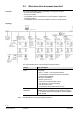
4 Installation – overview 4.1 PXC3... The illustration is a diagram of a PXC3 room automation station in an installation box / panel, the TX-I/O modules, connections to the field devices as well as bus connections (Ethernet, KNX, DALI).. Insert Ethernet MS/TP Installation box / cabinet KNX PL-Link 24 V DALI AC 24 V Island bus M Element T1 AC 24 V N1 U1, U3 U2 U4 U5 ---Ethernet KNX PL-Link DALI Description Transformer AC 24 V à transformer sizing Wiring of power lines and island bus PXC3...
4.2 DXR2... The illustrations are diagrams of DXR2 room automation stations in an installation box / panel, the connections to the field devices as well as bus connections (Ethernet, MS/TP, KNX, DALI)..
5 Installation box / panel for TRA 5.1 Requirements Systems with TX-I/O modules Please read Sections 5.1 "Panel requirements" and 5.3 "EMC compliant panel" in the TX-I/O engineering and installation guide [8] prior to engineering and executing the installation box. Space requirements Observer the following for mounting and installation.
5.2 Requirements Layout The table below provides information on general installation box / panel requirements. Check to ensure the individual requirements are met. Bullet Mechanical execution Requirements Construction, stability and sealing meet applicable regulations at the plant's location. Ambient conditions · Desigo TRA is designed for an ambient temperature of -5 - 50°C / 23...122 °F. PXC3.E7x and DXR2...: 45°C / 113 °F for certain mounting positions, see below.
5.3 Geometric design 5.3.1 Mounting position The mounting position is equivalent to the direction of the device labeling. TX-I/O devices and PXC3.E16A can be mounted in any position: Recommended · Wall, horizontal from left to right or from right to left · Wall, vertical from top to bottom or from bottom to top. Ambient temperature -5...50 °C / 23...122 °F Permissible · Over head. · On a horizontal surface. Ambient temperature -5...50 °C / 23...122 °F For the PXC3.x.7x types and DXR...
DXR2... PXC3...
5.4 EMC compliant installation box / panel Below only installation boxes are mentioned. Panels are included. Introduction One purpose of the installation box is to reduces electromagnetic interference. The influence depends on the internal and/or external EMC interference. The internal EMC disturbance can be, for example, an inverter in the same installation box; an external disturbance a nearby RF transmitter. The installation boxes are the reference point for shielding cables and housings.
5.5 EMC compliant wiring Below only installation boxes are mentioned. Panels are included. Wiring rules If heavy EMC disturbance is expected in an installation box or in the building, the following wiring rules can better protect TRA devices: Installation box wiring · In the installation box, separate unshielded lines from shielded lines at the terminal connections and cable ducts. · Avoid cable loops. · Plan sufficient space to correctly connect the cable screens.
Attaching cables to the installation box Strain relief of cables is done on the outside of the installation box. Attaching cables in the cabinet Cable screens for screened/shielded wiring must be installed as close as possible to the cabinet inlet on its metal structure and connected to the building's ground system. The following illustrations display the correct connections for shielded and unshielded cables to the screen and cable fastening rails.
6 Wiring of power lines This section describes the wiring between the transformer and power point(s) (Room automation station, power supply module, bus connection module). Note Detailed information on wiring for AC24V and island bus is available in the TX-I/O engineering and installation guide CM110562 [8]. 6.1 Safety notes Supplemental notes on safety Before starting the wiring, please comply with "Important information on safety" in Section 3. The following notes are closely related to Section 3.
. 6.2 AC 230 V power lines 6.2.1 DXR2, RXM · The sizing and fusing of the power lines are oriented to overall load and local regulations. · Devices with AC 230 V supply can be wired in line topology. However, the next device has no AC 230 V power when a room automation station is removed. The connection exists only on the board, but not on the terminal block. DXR2 RXM... · External fuse max. T 10 A (protection of the PCB tracks to the load circuits / relays). Max. load of the lines: 6 A.
6.2.2 AC 230 V power line cables · The sizing and fusing of the power lines are oriented to overall load and local regulations. · Fuse max. T 10 A (protection of the PCB tracks to the load circuits / relays). · Supply cables must be secured with cable restraints. · The AC 230 V installation must guarantee that the voltage is at least 230 V -15% = 196 V at the location of the room automation station.
6.3 AC 24 V power lines 6.3.1 PXC3 (power and island bus lines) The following diagram illustrates basic wiring for power lines for modular room automation stations using AC 24 V operating voltage as per PELV (Grounding of ^ near the transformer). SELV without grounding is also admitted. Installation box 1 ß Installation example L L N AC 24 V 24V~ T1 AC 24 V T2 24V~ F2 ...A 24V~ 24V~ F1 ...
Basic circuit diagram (connections AC 24 V, fusing) 1 + 2 4 3 ~ KNX 2) 24V/2A 5 ~ 6 24V~ 7 ~ 8 24V~ PTC KNX Island bus CS M 10A 9 1), 2) 3) Secure operation STOP Note! Communications STOP Note! 10 11 + DALI 3) 12 Island Bus 1) 9203z05_02 DALI V~ Not with PXC3.E16A-100A, PXC3.E16A-200A Only with PXC3.E...A... types · The next device has no AC 24 V power when a room automation station is removed. The connection exists only on the board, but not on the terminal block.
6.3.2 DXR2 / DXR1 · Topology: DXR2... room automation stations with AC 24 V supply can only be wired in star topology or with stubs (no daisy chain wiring). · DXR2.E... / DXR1.E… : AC 24 V grounded or not grounded · DXR2.M... / DXR1.M… : AC 24 V ^ must always be earthed at the transformer. · Consumption: DXR2... room automation stations with AC 24 V supply are limited to a consumption of 4 A / 100 VA. · The devices have an internal 4 A fuse which CANNOT be replaced.
Communications STOP Note! If USB communications do not work, this is an indicator that the AC 24 V operating voltage is incorrectly wired (conductors V~ and ⏊ inverted). 6.3.3 AC 24 V Transformer sizing The engineering responsibility includes transformer sizing. The selected transformer rating is based on the total power consumption of the automation station, the I/O modules and the connected field devices. Operating voltage · The operating voltage is AC 24 V.
Power consumption TX-I/O: Consumption data DC 24 V per I/O point Values in mA, for DC 24 V supply sizing (max. 600 mA from the PXC3, otherwise separate power supply module(s), for details see [7]). TXM1.6RL TXM1.8RB TXM1.8T Digital input (contact closed) Analog input 3) (Temp. sensors Ni, PT, T1) 3) Analog input (Temperature sensor NTC) Analog input 3) (Resistance) 2) Analog input (10 V) TXM1.6R 2) 35 20 25 25 10 8 12 8 TXM1.16D 1) TXM1.8D Intrinsic consumption TXM1.8U Type 25 25 3.
Power consumption of the triacs on DXR2 AC 24 V Per triac Unconfigured triac (Reserve for later configuration) 6 VA / 250 mA 6 VA / 250 mA Thermal actuators with a starting power of 6 VA (not pre-heated): If driven by a 5...50% PWM signal, they only count for 3 VA. Power consumption of the triacs on DXR1 AC 24 V Per triac Unconfigured triac (Reserve for later configuration) 12 VA / 500 mA 12 VA / 500 mA Max. power consumption of DXR2 / DXR1 AC 24 V Due to internal heat dissipation, the max.
6.3.4 AC 24 V power line cable lengths The permissible voltage drop of 0.48 V (2%) on the power wire between the transformer and the most distant power point (room automation station, power supply module, bus connection module) is the basis for calculations. The table below provides cable lengths and cable cross sections based on load. Cable cross-section Power 2.50 mm2 / AWG14 1.50 mm2 / AWG16 1.
6.4 Power supply for field devices Most of the TRA devices have a built-in power supply for field devices Type TXM1.8U Data sheet N8173 AC 24 V Fusing DC 24 V Fusing KNX field supply (terminals 3 and 4) Fusing ..4 A 10 A 5) DXR2.x09 AC 230 V N9204 N9206 4 VA 2) 3) 4) DXR2... AC 24 V N9205 N9207 12 VA 1) DXR2.x18 PXC3 RXM39.1 N9205 N9207 18 VA N9203 N3836 144 VA 10 A 4) 6 VA 1) 1) 1) 2.4 W 1) 48 VA 1) Note! 1) Short circuit proof.
7 Wiring of field devices (without bus) This section describes the wiring between the room automation station / the TX-I/O module and the field devices. 7.1 Signal wiring The following applies in common for signal wiring of field devices such as temperature sensors, window switches, presence detectors, dew point sensors or electrical buttons, as well as DC 0...10 V devices: Cable material · Use stranded, 2 or multiple core round cables, without screen (standard off-theshelf installation cable).
7.1.1 Common ^ conductor with multiple contacts Connection diagram (Example) Digital inputs When several status or counter contacts are to be connected, a common ^ conductor may be used. This saves wiring. However, system ground must be connected at least once per room automation station / per TX-I/O module.
Another limiting factor for cable length is hum injection for certain sensitive signal types: Hum injection Signal type TXM1.8U DXR2... AI NTC100K AI NTC10K All other signal types AI NTC100K AI NTC10K AI NTC3K AI R100K All other signal types Normal hum mAeff Can be maintained with cable length ----0.5 300 m / 1000 ft Reduced hum mAeff Can be maintained with cable length / shield 0.05 30 m / 100 ft (80 m with shield *) 0.05 30 m / 100 ft (80 m with shield *) 0.05 300 m / 10000 ft -- -- 0.
Measured value error T1 sensors T1 sensors: Measured value error due to line resistance: F [K] 1.0 1 mm ² 0,6 mm Ø 0.8 1,5 mm² 0.6 0.4 2,5 mm² 0 -0.1 100 2·L Formula: F = Key Measured value error NTC sensor 57 · A 10 200 300 L [m] 10762d055 0.2 -1 Cable cross-section in mm2 Measured temperature error in K Cable length in m A F L Measured value error of NTC sensors due to line resistance: The sensors are highly non-linear.
7.1.3 Active sensors and actuators DC 0 … 10 V The permissible length of DC 10 V cables for signals, and of the cables to supply the devices, have to be calculated on the following basis for each device (see also the relevant device data sheets): – Max. 7 % voltage drop (1.68 V) on the cables due to the sensor supply current. Reason: to ensure sufficient voltage for the device supply. – Active sensors: Measuring error of max. 0.
These devices have an internal rectifier, to convert AC 24 V to DC 24 V. This causes a DC current to flow in the system neutral conductor (^) which causes a voltage drop over the line resistance. This voltage drop falsifies the DC 0...10 V signal value. The cable length must be reduced to limit the signal error (0.5% for sensors, 1% for actuators). Cable length for devices with AC/DC 24 V Sensors Cable cross section Power 2 2.50 mm / AWG14 1.50 mm2 / AWG16 1.00 mm2 / AWG18 0.
7.2 Wiring for Triac outputs AC 24 V The following applies for wiring to actuating devices such as valves, damper actuators or protection connected to the Triac outputs: Cable material · Use stranded, 2 or multiple core round cables, screened (standard off-the-shelf installation cable). · Single wires may not be used. Cable laying · Wiring may be laid together with power lines (AC 230 V). They must be isolated from the power lines per regulations. Isolation must meet PELV requirements.
7.3 Wiring for Relay outputs · External fuse of max. T 10 A for protection of the PCB tracks. · The maximum load of the relay contracts must be observed (see data sheets for the corresponding devices). It may require a fusing <10 A. · Relays have volt-free relay contacts. The mains voltage / switching voltage (AC 230 V / AC/DC 24 V) must be supplied as an external voltage to the terminals. · The lines must be secured on the device with strain relief.
8 Electrical features of inputs & outputs 8.1 Digital inputs Digital inputs are not electrically isolated from the system electronics. Mechanical contacts must be volt-free. Electronic switches must comply with SELV or PELV standards. Technical data Contact sensing voltage Contact sensing current Insulation resistance with contacts closed Contact resistance with contacts open Measured value acquisition and measured signal DC 17...25 V 1.0...1.6 mA (initial current 6...10 mA) Max.
8.2.2 Active sensors DC 0 … 10 V The active sensors use a signal amplifier which emits a standard DC 0...10 V signal. This voltage range is proportional to the application range of the sensor.
8.2.3 Compensation of the line resistance Signal type Resistance AI 1000 Ohm Resistance AI 2500 Ohm Technical data for the analog inputs 1 Ohm, calibrated in the module, (except for NTC3K, NTC10K, and NTC100K) TX-I/O Range (Under / over range) 3) 0...2500 Ohm (0...2650 Ohm) 0...2500 Ohm (0...2650 Ohm) Resolution 100 mOhm 100 mOhm Resistance AI 100 kOhm -50…150 °C (-52.5 ...185.0 °C) -50...400 °C (-52.5...610°C) -50...150°C (-52.5...155.0 °C) 10 mK 0.018 °F 20 mK 0.036 °F 10 mK 0.018 °F -50...
8.3 Digital outputs (relays, triacs) 8.3.1 Admissible relay load Type Data sheet General use Fan stages Fan release TXM1.6R... N8175 4 (3) A 4 (3) A 4 (3) A Electric reheater (4 (3) A) DXR2... N9204ff 4 (3) A 4 (3) A 4 (3) A RXM21.1 N3835 RXM39.1 N3836 5 (4) 5 (4) (Q34) 1,8 kW ohm load (Q14) 10 A 3A 8.3.2 Type Admissible triac load TXM1.8T Signal type 3) 4 VA 1) 6 VA 2 x 4.5 VA DXR1... 5) AC 24 V A6V11393931 A6V11393933 A6V11393929 12 VA DXR2...
8.3.3 Firmware functions Triacs and AO 0-10V on DXR2 AC 230 V: engineering AC 24 V is produced internally. The max. admissible continuous load for triacs and field supply is 4 VA (6 VA during 300 s for the starting load of thermal actuators in cold condition). The firmware features the following mechanisms to avoid overload: · Internal prioritization of commands "AO 3-position", "AO PWM Const. period" and "AO PWM Thermal" so that only one triac is active at a time.
Summary: The maximum overall load is calculated as follows: Overall load: Highest load at one of the Triacs with motorized or thermal actuator + Load at digital outputs + Load a field supply 1) Examples Triac Example 1: DXR2x10.., 09T Use Type Fan coil heating STP73 Chilled ceiling STP73 Outside air damper GEB131.1E Overall load Example 3: DXR2.x09 Use Radiator Chilled ceiling Overall load Type 4 x SSA81 4 x SSA81 Example 4: DXR2.
8.4 Analog outputs DC 0...10 V Technical data Output voltage TX-I/O DXR2 Output current Signal type Range (under / over range) Resolution AO 0-10V AO 0-10V AO 0-10 V norm 0 … 10 V (-0.05...10.6 V) 0 … 10 V (0...10.5 V) 0...100% (0...10,5 V) 0% = 0 V, 100% = 10 V 1 mV 2 mV 2 mV max.
9 Ethernet network 9.1 IT security · Building automation and control systems must use a separate technical network with very restricted and selective connection to the rest of the intranet and no connection at all to the internet. This can be done using a VLAN or a separate subnet. · If access from the rest of the intranet is required: Use a router with very selective bridging. · Prevent unauthorized access to any infrastructure (e.g.
Note! Availability / reliability · The next device has no AC 24 V power when a room automation station is removed. The connection exists only on the board, but not on the terminal block. · The Ethernet switch is inactive when a room automation station has no AC 24 V power. The next devices, if in line topology, are disconnected from the network. For secure operation of the system it is recommended to supply each room automation station separately with AC 24 V. 9.
* AC 24 V Ethernet PoE switch PoE 11043z20 PoE PoE switch * Supply voltage and power depend on the type of PoE switch used and the number of connected room operator units. Function In PoE, power sourcing equipment (PSE) supplies power to powered devices (PD, here: end devices). Voltage is supplied via the RJ45 plugs and a twisted-pair cable (TP) to the devices either: 1. Via data transmission lines 2. Or via unused lines of the RJ45 connection. PoE topologies PoE requires a star topology.
10 MS/TP networks 10.1 Network requirements Topology · The MS/TP network must be inside the building. The cables must never leave the building. · BACnet MS/TP networks for Desigo TRA can only be wired in line topology. T-taps (T-junctions) are not allowed, except for stubs (max. 30 m). Restrictions for DXR2.M... Whereas HVAC functions are not time-critical, lighting and blinds require a visible response within 0.25 s.
Network settings Note! Number of devices · The Desigo TRA devices communicate with up to 115,200 bps. · All devices must be set to the same speed. Otherwise, no communication is possible. · APDU timeout and APDU segment timeout recommendation: 16 devices: 6 sec 32 devices: 10 sec. · Set Max Master for all devices. · Set router address to 0. · Set Max Info Frame to 50 in the router. · Set Max Info Frame to 10 in the DXRs (default). · In case of communication problems, the speed can be reduced via tool.
· Grounding of the shield at ONE end of the network segment. Key +, – Twisted pair 120 Ohm Bus terminating resistor (½ W 5%) at BOTH ends Reference wire PTC Special-thermistor (TRF250-120) at ONE end Shield Note! Availability Additional information · The next device has no power (AC 230 V) when a room automation station is removed. The connection exists only on the board, but not on the terminal block.
10.2 Technical data BACnet MS/TP Communications on BACnet MS/TP networks take place over EIA-485 physical media. 3-wire RS-485 network interface · Desigo TRA devices use the 3-wire interface without noise suppression. Therefore, the cables must provide noise protection. This is guaranteed by the reference wire and the shielding. · The interface is protected against short circuit, wrong polarity and faulty wiring with AC 24 V. However, communications do not work with wrong polarity.
Examples of recommended cable types Belden Type 9925 8102NH 1419A Capacitance 39 pF/m 12 pF/ft 41 pF/m 12.5 pF/ft 43 pF/m 13.1 pF/ft Nonhalogen NH Shield Pairs Foil + Braid Temperature 80 1.5 Black Red White Foil + Braid 80 2 2) Foil 80 2 2) Blue White / White Blue Orange White / White Orange Blue White / White Blue Orange White / White Orange 1) Color 3) 1) Foil + Braid is recommended for harsh environment (mechanical and electromagnetic interference, e.g. variable speed drives).
11 Use SCOM sensor bus SCOM provides dedicated digital sensor communication: · Interface type · · · · · · · Connection of SCOM devices is connected RS485 – non-insulated (reference wire to system neutral ⏊) Baud rate 115200 Cable type KNX or BACnet MS/TP cable, e.g. Belden 9925 Max. cable length 800 m (2600 ft) Topology Line Network terminators (120 Ohm, 0.
12 Island bus This chapter is only a brief overview of the island bus installation. The TX-I/O engineering and installation guide 10562 [7] includes detailed information on island bus wiring and island bus extension for PXC3 room automation stations and TX-I/O modules. · Island bus and island bus expansion are designed for indoor use in one building only. · PXC3 room automation stations each have switchable TX-I/O DC 24 V / 600 mA module power supply. They are switched on at the factory.
13 KNX PL-Link room bus · The KNX PL-Link bus must be inside the building. The cables must never leave the building. · The KNX PL-Link bus facilities communications from the PXC3 room automation station to a maximum 64 devices on the KNX bus devices for various manufacturers. · Note: The number of devices is also limited by the number of data points and the available bus power. Bus power is incremented during engineering with the ABT tool.
13.1.2 External bus supply If the 160mA of the PXC3 / the 50 mA of the DXR2 are insufficient to cover the power demand of the connected devices, the internal bus power supply must be switched off via tool and replaced by an external bus power supply unit (PSU). Power supply units for 80,160, 320 and 640 mA available in specialty stores. The total power supply for the devices must be calculated to determine the appropriate size. Comply with the corresponding details in the datasheet.
13.2 Bus topologies Up to 64 devices with KNX PL-Link can be installed on one line (main line as well). No restrictions apply to the type mix. 64 devices on one line Notes · There is no need to calculate the bus load number E for up to 64 devices. · A maximum of 64 devices may be installed even if devices requiring less power are used. Permissible bus topologies Permissible bus topologies are: Tree, line, and star topologies. These topologies can be mixed as needed.
13.3 Cables Bus cable selection + KNX KNX The bus lines (= twisted pair) are connected via PL+ (red) and PL– (black). - + - AC 24 V T Bus lines Choose the bus cable as per country-specific offerings. Comply with values indicated in this document under "Technical data KNX PL-Link". AC24V for field supply can be provided in the same (2 x 2 stands) or in a separate cable.
Notes Power supply AC 24 V PXC3 only · At least one supply (internal or external) is required for each line, and max. two supplies (external) are allowed per line. · Install the power supply unit as close to the network center as possible to achieve maximum line size. · The distance between the device and the next neighboring PSU may not exceed 350 m / 1100 ft. As a result: Even if the power demand from the devices does not require it, two power units must be used depending on the line length.
13.5 Technical data KNX PL-Link KNX bus Transmission medium (bus cable) Baud rate Bus line polarity Bus terminating resistor Communication signal The communication signal (information) is transferred symmetrically, i.e., as voltage difference between the two bus lines (and not as a voltage difference to the earthing potential). The sign preceding the voltage between PL+ and PL– determines signal values 0 and 1.
14 DALI network · The DALI network allows the PXC3 room automation station to communicate with DALI ballasts and sensors. · DALI is a two wire bus. The signal conductors can be in the same cable as the AC 230 V power for the lights, or in a separate bus cable. · The PXC3 possesses a DALI bus supply to power DALI devices. Additional information Detailed information is available on the DALI homepage at www.dali-alliance.org. 14.
NOT admissible: · 28 lights with onboard sensor 28 x (2mA + 5 mA) = 196 mA · 50 lights, 1 sensor per 2 lights 50 x 2 mA + 25 x 5 mA = 225 mA 14.2 Bus topologies DALI devices in a circuit Up to 64 DALI ballasts and 63 DALI-2 sensors may be installed on one DALI circuit. No restrictions apply to the type mix. Permissible bus topologies Permissible bus topologies are: Tree, line, and star topologies. These topologies can be mixed as needed. However, ring topologies are not allowed.
The overall length is 300 m / 1000 ft for a wiring cross-section of at least 1.5 mm2. Admissible cable lengths Note . Regulations The permissible voltage drop off over the DALI line and the terminals is a maximum of 2 V. The voltage drop off over the DALI line is typically 90% of 2V (1.8V) and via the terminals 10% of 2V (0.2V). Must comply with low-voltage installation regulations since the DALI signal is not SELV.
15 EnOcean RF networks 15.1 Technology (This section is based on the document "EnOcean Range planning" by Engineer Armin Anders, EnOcean LLC). The patented EnOcean RF technology creates a surprisingly far-reaching signal with remarkably little energy. So that devices can be operated trouble-free without solar cells, Piezo elements or thermocouples. The patented EnOcean RF technology creates a surprisingly far-reaching signal with remarkably little energy.
Interoperability · RF protocol is defined and integrated in the modules. · Sensor profiles are established and followed by users. · Unique transmission ID (32 bit). Coexistence with other RF systems · No interference with DECT, WLAN, PMR systems, etc. · System design verified in an industrial environment. Specially suited for · Renovation projects (old buildings, museums, churches, historical buildings, etc.).
sent. Moreover, some events are sent with a ca. 2-minute delay or immediately. For details, see the technical data "Frequency of transmission". The room device stops transmitting if the energy store is not charged sufficiently and/or the battery is empty. 100% functionality cannot be guaranteed under all circumstances. There are simply too many possible sources of interference, both legal and illegal, impacting range tremendously.
Definition: Illuminance Brightness refers to how the human eye perceives the intensity of a light source. Brightness is measured in Lux [lx]. The human eye can perceive various light sources with the same brightness. Depending on the technology, solar cells have varying degrees of efficiency for daylight and artificial light. Fluorescent lights require at least 30% greater brightness to generate the same level of charging as daylight.
Business Showroom Sports facility Notes on mounting location of room units Restaurant Bathrooms Bars Hallways Stairwells Sales room Showroom Packaging area Break room Conference room Both Interior 150 - 300 lx. 100 - 300 lx. 50 - 150 lx. 50 - 100 lx. 50 - 150 lx. 300 - 1000 lx. 500 - 1500 lx. 200 - 300 lx. 300 - 500 lx. 300 - 700 lx. 300 - 500 lx. 200 - 500 lx. · Select the best compromise between Illuminance, ventilation locations and aesthetic requirements.
15.3 Battery operation This section refers to room units equipped with solar cells. Normally, ambient light suffices to charge the energy store required to operate the room device. If, however, lighting conditions at the mounting location are insufficient to meet guide values provided in Section 15.2 "Lighting conditions at mounting location", insert a battery in the battery holder. This ensures device operation even under unfavorable lighting conditions. Use a lithium button cell battery (type CR2032).
A radio signal's strength decreases with distance as it is sent in all directions. In addition, other factors influence the radio signal strength. Radio signal range Below are a few examples of interference and attenuating impact of different materials. Material: Wood, gypsum, uncoated glass Brick, pressboards Reinforced concrete Metal, aluminum lamination Transmitter Metal Passage of radio signals 90...100 % 65...95 % 10...90 % 0...
15.5 RF signal range Planning RF networks Since RF signals are electromagnetic waves, the field strength at the receiver decreases as the distance to the transmitter increases, in other words, the RF range is limited. Any materials in the transmission field reduces the range accordingly. RF waves do penetrate walls, but dampen the strength versus pure line of sight.
RF signal shielding Metal surfaces reflect electromagnetic waves, e.g. metal partitions and metal ceilings, massive steel reinforcement in the concrete walls and metal foils from insulation. Creating RF shading in a "silent zone". Individual, thin metal strips have little impact, for example, strips in a gypsum drywall. Metal surfaces Mounting a transmitter directly on a metal surface (e.g. panel doors, steel door frames) prevent the free transmission of the RF signal.
Penetration angle The angle at which a transmitted signal hits the wall plays an important role. The effective wall strength and thus the dampening of the signal depends on the angle. The signals should run vertical to the walls as much as possible. Avoid wall recesses as much as possible. Solution Eliminate excessively flat penetration angles by repositioning the transmitter and/or receiver antenna or use a repeater.
>10 cm >4 in Mounting magnetic foot antenna Tip Mounting patch antenna When laying the antenna cable it is important not to bend the cable, causing irreparable damage (reduction in performance caused by a change to wave resistance). A "active antenna" is a RF receiver with integrated antenna. It communicates with an actuator unit, for example, via a simply RS485 cable (RS485 Gateway).
Field strength measuring equipment Off-the-shelf field strength measures devices that easily find the best mounting locations for transmitter and receiver. Faulty connection from previously installed devices can also be reviewed. The RF telegrams and disruptive RF signals are displayed in the relevant frequency range. Additional information available at: http://www.enocean-alliance.org/de/home.
15.6 Range planning RF range is typically limited by fire protection walls that are considered shielding. Within fire protection areas, light walls or glass partitions with solid RF properties are often used. Avoid metal reinforcement or metalized glass!. The following diagrams illustrate how to implement a reliable RF plan in three steps.
STEP 3: Draw range circles · The center of the circle represents the ideal position for RF gateways. · This allows for a shield-free connection in all corners of the fire protection section (possible sensor positions). Real-world experience suggests that unfavorable conditions and shortcomings are commonplace. Planning at 10-12 meter radiuses provide a high level of security; against future changes to environmental changes as well (light walls, furniture, personnel in the room, etc.).
15.7 Troubleshooting Trouble free operation of the devices is normally guaranteed if you follow all the notes on the selection of mounting locations for transmitters and receivers. The following overview of potential problems may help should problems nevertheless arise: Transmitter is not received Check with EPM100 In close proximity to the transmitter (distance approx. 20-50 cm / 10-20 in), the EPM 100 does not receive any transmission telegrams.
Transmitter is occasionally not received Check with EPM100 In close proximity to the receiver antenna (distance approx. 20-50 cm / 10-20 in), the EPM 100 receives transmitter telegram at the limits. Trigger transmission telegram, the corresponding LO/HI LED is unlit on the EPM. (HI for flush-mount receiver; LO for receiver with external antenna). Possible cause and solution a) Transmitter is within the limits of the transmitter. Move the transmitter or receiver antenna or use a repeater.
15.8 Commissioning RF link For operation, the connection to the gateway must first be set up. See data sheet N1661 (Gateway EnOcean/LonWorks) or N1662 (Gateway EnOcean/KNX). Send "Init" telegrams The LEARN button is located on the lower section of the housing below the battery. Press this button to create and immediately send a complete learning telegram. The current switching status of LEARN – pressed – is also transmitted.
16 Disposal The device is considered an electronic device for disposal in accordance with the European Guidelines and may not be disposed of as domestic garbage. · Dispose of the device through channels provided for this purpose. · Comply with all local and currently applicable laws and regulations.
Published by: Siemens Switzerland Ltd. Smart Infrastrructure Global Headquarters Theilerstrasse 1a 6300 Zug Switzerland Tel. +41 41-724 24 24 www.siemens.