
Installation Instructions


2 / 86
Siemens Desigo Room automation - Engineering, mounting and installation CM111043en_14
Smart Infrastructure Contents 2020-10-30
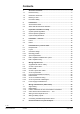
Contents
1 About this document ........................................................................... 4
1.1 Revision history ..................................................................................... 4
1.2 Reference documents ............................................................................ 4
1.3 Before you start ..................................................................................... 5
1.4 Document validity .................................................................................. 6
2 Introduction ......................................................................................... 7
2.1 About this document .............................................................................. 7
2.2 What does this document describe?....................................................... 8
3 Important information on safety ....................................................... 10
3.1 System-specific regulations ................................................................. 10
3.2 Device-specific regulations .................................................................. 12
3.3 Cyber security Disclaimer .................................................................... 13
4 Installation – overview ....................................................................... 14
4.1 PXC3... ................................................................................................ 14
4.2 DXR2................................................................................................... 15
5 Installation box / panel for TRA ......................................................... 16
5.1 Requirements ...................................................................................... 16
5.2 Layout ................................................................................................. 17
5.3 Geometric design................................................................................. 18
5.3.1 Mounting position ................................................................................ 18
5.3.2 Space requirements ............................................................................. 18
5.4 EMC compliant installation box / panel ................................................. 20
5.5 EMC compliant wiring .......................................................................... 21
6 Wiring of power lines ......................................................................... 23
6.1 Supplemental notes on safety .............................................................. 23
6.2 AC 230 V power lines .......................................................................... 24
6.2.1 DXR2, RXM ......................................................................................... 24
6.2.2 AC 230 V power line cables ................................................................. 25
6.3 AC 24 V power lines ............................................................................ 26
6.3.1 PXC3 (power and island bus lines) ...................................................... 26
6.3.2 DXR2 / DXR1 ...................................................................................... 28
6.3.3 AC 24 V Transformer sizing ................................................................. 29
6.3.4 AC 24 V power line cable lengths......................................................... 32
6.4 Power supply for field devices .............................................................. 33
7 Wiring of field devices (without bus) ................................................ 34
7.1 Signal wiring ........................................................................................ 34
7.1.1 Digital inputs ........................................................................................ 35
7.1.2 Passive resistance sensors and resistance transmitters ....................... 35
7.1.3 Active sensors and actuators DC 0 … 10 V .......................................... 38
7.2 Wiring for Triac outputs AC 24 V .......................................................... 40
7.3 Wiring for Relay outputs ....................................................................... 41
7.4 Connecting the differential pressure sensor.......................................... 41
8 Electrical features of inputs & outputs ............................................. 42