Industry Automation and Drive Technologies - SCE Training Manual for Integrated Automation Solutions Totally Integrated Automation (TIA) MODULE E12 VISION SENSOR Shape Checking with SIMATIC S7-300F-2 PN/DP and VS120 TIA Training Document E12 Status: 01/2010 Page 1 of 47 Module Vision Sensor Shape Check with SIMATIC S7-300F 2PN/DP and VS120
Industry Automation and Drive Technologies - SCE This manual was prepared for training purposes by Siemens AG for the project Siemens Automation Cooperates with Education (SCE). Siemens AG does not guarantee the contents of this document. Passing on this document as well as copying it, using and communicating its contents is permitted within public training and continued education facilities. Exceptions require the written permission by Siemens AG (Michael Knust michael.knust@siemens.com).
Industry Automation and Drive Technologies - SCE PAGE 1. Preface.....................................................................................................Fehler! Textmarke nicht definiert. 2. Notes on using the CPU 315F-2 PN/DP .........................................................................................................7 3. Notes on the SIMATIC VS120 components....................................................................................................7 4. 5. 6. 3.1.
Industry Automation and Drive Technologies - SCE The following symbols serve as a guide through Module E12: Information Programming Sample Task Notes TIA Training Document E12 Status: 01/2010 Page 4 of 47 Module Vision Sensor Shape Check with SIMATIC S7-300F 2PN/DP and VS120
Industry Automation and Drive Technologies - SCE 1 PREFACE Regarding its content, Module E12 is part of the instruction unit ’IT Communication with S7’.
Industry Automation and Drive Technologies - SCE Hardware and software required 1 2 3 4 5 PC, operating system Windows XP Professional with SP2 or SP3/Vista 32 Bit Ultimate and Business/Server 2003 SP2 with 600MHz (only XP)/1 GHz and 512MB (only XP)/1 GB RAM, free disk storage approx. 650 to 900 MB, MS Internet Explorer 6.0 and network card Software STEP 7 V 5.4 SPS SIMATIC S7300 with CPU 315F-2 PN/DP and at least one digital input and output module.
Industry Automation and Drive Technologies - SCE 2 NOTES ON USING THE CPU 315F-2 PN/DP The CPU 315F-2 PN/DP is a CPU that is shipped with 2 integrated interfaces. - The first interface is a combined MPI/PROFIBUS DP interface that can be used at the PROFIBUS DP as master or slave to connect distributed IO/field devices with very fast reaction time. In addition, it is possible to program the CPU here by means of an MPI or PROFIBUS DP - The second interface is an integrated PROFINET interface.
Industry Automation and Drive Technologies - SCE 3.
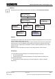
Industry Automation and Drive Technologies - SCE 3.4 Recording and Reading Out Recognition Values in a PROFINET IO Environment • By means of the Ethernet (TCP/IP) and a switch, a PC/PG is connected that is used exclusive for the setup process. • By means of the Ethernet and a switch, a connection exists to an automation systems with PROFINET IO capability. • The SIMATIC VS120 is controlled by the automation system.
Industry Automation and Drive Technologies - SCE 3.5 Setting the Communication Interface of the VS120 to PROFINET First, switch on the power supply of the evaluation device VS120 for the initial startup. At the initial startup, "Factory Settings Used" appears on the LCD display. Confirm with "OK".
Industry Automation and Drive Technologies - SCE "Connect" Menu: The Ethernet IP mode has to be set to PNIO. Place the cursor in front of Ports and press the OK button Place the cursor in front of Ethernet and press the OK button Place the cursor in front of IP Mode and press the OK button Place the cursor in front of PNIO and press the OK button The evaluation device now requests a restart; press the OK button to confirm.
Industry Automation and Drive Technologies - SCE 4 STARTING UP A PROJECT WITH CPU 315F-2 PN/DP AND VS120 Below, starting up the VS120 in a project is described. As SIMATIC S7-300 Station, the CPU 315F-2 PN/DP is used. In the CPU’s control program, a data structure has to be generated by means of a function block call (FB1) with data block (DB10).
Industry Automation and Drive Technologies - SCE 4.1 Setting Up a New Project 1. The central tool in STEP 7 is the ’SIMATIC Manager’. It is called here with a double click (→ SIMATIC Manager) 2. STEP7 programs are managed in projects. We are now setting up such a project (→ File → New) 3.
Industry Automation and Drive Technologies - SCE 4. Next, highlight your project and insert an ’Industrial Ethernet Subnet’. (→ VS120 → Insert → Subnet → Industrial Ethernet). 5.
Industry Automation and Drive Technologies - SCE 4.2 Configuring the Hardware 6. With a double click, open the configuration tool for the ’Hardware’. (→ Hardware) 7. Open the hardware catalog by clicking on the symbol ' ’. (→ ) Insert the ’Mounting Channel’ with a double click (→ SIMATIC 300 → RACK-300 → Mounting Channel). Note: Then, a configuration table is displayed automatically for setting up Rack 0.
Industry Automation and Drive Technologies - SCE 8. Now, from the hardware catalog select all modules that are also inserted in your actual rack and place them in the configuration table. To this end, click on the name of the respective module, hold the mouse key and drag it to a line in the configuration table.
Industry Automation and Drive Technologies - SCE 9. Next, we drag the ’CPU 315F-2 PN/DP’ to the second slot. The CPU’s order number and the version are provided on the front of the CPU. (→ SIMATIC 300 → CPU-300 → CPU 315F-2 PN/DP → 6ES7 315-2FH13-0AB0 → V2.6) 10. When entering the CPU, the window below is displayed. In this window, do the following: assign to the CPU 315F-2 PN/DP an ’IP Address’, specify the ’Subnet screen form’ and select the ’Ethernet’ that is already set up.
Industry Automation and Drive Technologies - SCE Notes regarding networking on the Ethernet (additional information is provided in Appendix V of the training manual): MAC address: The MAC address consists of a permanent and a variable part. The permanent part ("Basic MAC address") identifies the manufacturer (Siemens, 3COM, ...). The variable part of the MAC address differentiates the different Ethernet stations and should be assigned globally unique.
Industry Automation and Drive Technologies - SCE 11. Next, we drag the input module for 16 inputs to the 4th slot. The module’s order number is inscribed on the front. (→ SIMATIC 300 → DI-300 → SM 321 DI16x24VDC). Note: Slot 3 is reserved for interface modules and remains empty for that reason. The module’s order number is shown in the footer of the catalog.
Industry Automation and Drive Technologies - SCE 12. Then, we drag the output module for the 16 outputs to the 5th slot. The module’s order number is inscribed on the front. (→ SIMATIC-300 → DO-300 → SM 322 DO16x24VDC/0.5A). Note: The module’s order number is shown in the footer of the catalog. 13. Now, we have to change the PROFINET device name to PN-IOx100.
Industry Automation and Drive Technologies - SCE 14. Then, drag the PROFINET IO System (100) module tier <> toward the right, and from the folder PROFINET IO add the SIMATIC VS100 module VS120 by dragging it to the tier. If module VS120 should not be available for selection, it has to be added by a data carrier by means of the menu “Options“ Install GSD files. 15. Double click on the inserted module and change the device name to VS120x120 and the IP address to 192.168.0.120.
Industry Automation and Drive Technologies - SCE 16. Now double click on the control byte of the inserted module and change the address of the inputs to 10 and of the outputs to 20. auf 20 Hardware View 17. By clicking on ' TIA Training Document E12 Status: 01/2010 ’, the hardware configuration is stored and compiled.
Industry Automation and Drive Technologies - SCE 4.3 Assigning the Device Name 18. Highlight module VS120 and then select, via the menu “Destination system“, at Ethernet ’Assign device name’. Note: A precondition for this is that the PG/PC interface is set to TCP/IP and the network card for the PC is configured correctly. For example, IP address 192.168.0.99, subnet 255.255.255.0 and router address -.-.-.- (refer to Module E02). 19. Highlight the VS100 module and then click on the button “Assign name“.
Industry Automation and Drive Technologies - SCE 20. By clicking on ' ’, we can now load the hardware configuration into the PLC. The operating mode switch should be on Stop! (→ ). (After the hardware is loaded into the CPU, the red BF LED on the VS120 goes out) 21. Close the hardware configuration.
Industry Automation and Drive Technologies - SCE 4.4 Inserting Blocks and FB1 and DB10 into the Project From the template directory or from the Image Processing System SIMATIC VS120 V2.1 CD from the directory "Function Blocks“, de-archive and open the library VS120-2. Add FB1 and DB10 to the block folder of the project. Close the library. Note: Instead of library VS120-2, we can also de-archive the example program VS120_Examples. The file Vs120_Examples.
Industry Automation and Drive Technologies - SCE FB1 Input Parameters Declaration Data Type Description Address of the control byte in the SIMATIC VS120 interface that is entered under the Connection Control. This parameter has to be wired.
Industry Automation and Drive Technologies - SCE FB1 Output Parameters Notes ____________________________________________________________________________ ____________________________________________________________________________ ____________________________________________________________________________ ____________________________________________________________________________ ____________________________________________________________________________ ________________________________________________
Industry Automation and Drive Technologies - SCE 4.6 Operating FB1 Model Selection • To select a model, the DISA bit has to be set to 1. • The desired model number is set up at FB1 input MODEL. • The model change is completed when the TRD and RDY bit changes from FALSE to TRUE. The model number that was set up is placed on output MODEL_OUT. • As long as no model was transmitted, 0 is read out at output MODEL_OUT. • The output MODEL_OUT changes to 0 as soon as the DISA bit is reset.
Industry Automation and Drive Technologies - SCE 4.7 FB1 Error Information If an error occurs, ERROR = 1 is set. The exact cause for the error is indicated in ERRCODE. Error information • 0000: No error • 1xyz: Internal FB1error • 2xyz: Evaluation device error • 8xyz: Error indications of internal SFCs Explanation No error Impermissible model number (parameter model). The values 1 to 15 are permissible Impermissible reveive area. Only data type BYTE is permissible Impermissible data area.
Industry Automation and Drive Technologies - SCE Structure of the DB10 (DB10 has a size of 246 bytes and can accommodate 16 SubROIs) TIA Training Document E12 Status: 01/2010 Page 30 of 47 Module Vision Sensor Shape Check with SIMATIC S7-300F 2PN/DP and VS120
Industry Automation and Drive Technologies - SCE 4.9 Supplementing the Symbol Table Open the symbol table and enter the following symbol assignments. Save and close the symbol table. 4.10 FC10 Control Program In FC10, we now generate the control program for the Vision Sensor Module VS120. Generate FC10.
Industry Automation and Drive Technologies - SCE The input/output addresses of the VS120 (hardware) have to be entered at the first four input parameters of FB1. With input I0.0, the command for image pickup and for starting the evaluation is executed. With input I0.1, the error is reset if there is an error. With input I0.2, operating the VS120 manually is disabled. At input parameter RECV, DB10 is specified as ANY P#DB10.DBX1.0 BYTE 245. In DB10, data is entered starting with Byte 1.
Industry Automation and Drive Technologies - SCE 4.11 Calling FC10 in OB1 Double click on OB1. Enter symbolic name and symbol comment. Confirm with OK Enter Network 1. Save and close OB1. We now can load the program into the CPU.
Industry Automation and Drive Technologies - SCE 5. WEB SERVER BASED OPERATOR INTERFACE OF VS120 5.1 Setting Up and Evaluating the Model Open the Internet browser. As link, enter the IP address 192.168.0.120 of the VS120. To set the language, click on the German flag.
Industry Automation and Drive Technologies - SCE Click on Set up Sensor. On the left of the interface, you will see a selection of tasks in the form of buttons. Activate the desired task with a mouse click on the corresponding button. The associated dialog will then be displayed on the right side of the interface.
Industry Automation and Drive Technologies - SCE Click on the button Set up. Here, we specify the parameters for image pickup and image evaluation. To create patterns that can be recognized, edges -that is, the transition from light to dark or vice versa- of the image are used. Although the algorithm extracts the edges automatically, the user has to provide for an image rich in contrasts through optimum exposure; i.e.
Industry Automation and Drive Technologies - SCE Now click on the button Connections. Then click on the tab Integration or on the button Continue. As Trigger, set the source PROFINET IO. At Connection, set the output, OK/N_OK, and controller PROFINET IO. Click on Accept. Next, click on the button Training.
Industry Automation and Drive Technologies - SCE Then click on the button Continue, set the parameters and draw a circular ROI (Region of Interest) around the part. Click on the button Continue Additional information about the parameters is provided in Chapter 4.3 of the operating instructions "Image Processing System Vision Sensor SIMATIC VS120“. Under the tab Edges, interfering or unimportant edges can be removed.
Industry Automation and Drive Technologies - SCE Under the tab Test, the trained part is tested. Click on the button Continue.
Industry Automation and Drive Technologies - SCE Under the tab Save, save the model with the name Part1. Now click on the button Evaluate and start the evaluation mode. Set the CPU to Run and start the image evaluation with "Start“ (I0.0).
Industry Automation and Drive Technologies - SCE Evaluation result: Faulty part with the Number 1 is too large and milling is crooked.
Industry Automation and Drive Technologies - SCE 5.2 Setting Up the Model Set and Evaluating the Model Number Several models are to be trained and combined into a set. Train parts 2 to 5.
Industry Automation and Drive Technologies - SCE Parts 1 to 5 are to be combined into one model set. Click on the button Options. In the tab Extras under Multi-Model Use: select ON. Highlight Part1 to Part5. Save Part1 with the names Click on the button Accept. All additional information about operating the Web server based interface is provided in Chapter 9.3 of the operating instructions "Image Processing System Vision Sensor SIMATIC VS120“.
Industry Automation and Drive Technologies - SCE Now click on the button Evaluate and start the evaluation mode. Set the CPU to Run and start image evaluation with “Start“ (I0.0). The work pieces are recognized.
Industry Automation and Drive Technologies - SCE Even if the number is faulty, a parts assignment is still made by means of the shape.
Industry Automation and Drive Technologies - SCE 6 RESULTS OF IMAGE EVALUATION IN THE CPU 6.1 Web View of the Evaluation 6.
Industry Automation and Drive Technologies - SCE 6.3 Variable Table DB_Values 6.