
Installation Instructions


Installation Instructions
Document No. A6V11175916
October 30, 2017
EcoView™ MicroPad Controller Installation and System Start-up
Item Number A6V11175916, Rev. BA Page 1 of 9
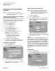
This document covers the installation of the
EcoView™ MicroPad Controller and startup of the
EcoView system. See the following documents for
installation of other EcoView system components:
• EcoView 8 DO Module Installation and
Commissioning (129-565)
• EcoView Thermostat Installation Instructions
(129-564 or 129-566)
• EcoView Multi-phase Meter Installation
Instructions (129-563)
Product Description
The EcoView MicroPad Controller is a full-color 7-inch
tactile display device, master controller and Internet
gateway built into a single wall-mounted unit.
Product Number
60-010
EcoView MicroPad controller/gateway
graphical user interface with ZigBee. (Includes
power transformer.)
Optional Product
97-003
EcoView ZigBee Repeater, universal input
voltage 85V to 265V, 2-prong plug.
Caution Notations
CAUTION:
Equipment damage or loss of
data may occur if you do not
follow the procedures as
specified.
Required Tools and Materials
• Drywall saw or appropriate tool for cutting drywall.
• Drywall anchors or molly bolts.
• One CAT5 cable which is long enough to run
between the EcoView MicroPad Controller
mounting location and the DSL/cable modem
or router.
Expected Installation Time
60 minutes
Prerequisites
• 100Base-T Ethernet connection is available.
• EcoView 8 DO Module and EcoView
Thermostat schedules are designed and
ready to be entered into EcoView Web.
• Ethernet port 80 is open or access to port 80
is available through a proxy server.
• An EcoView ZigBee Repeater (Digi Router)
(P/N 97-003) is available in case network
communication is troublesome because a
ZigBee device is out-of-range.
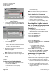
• If multiple EcoView MicroPad Controllers are
being used at the site, do the following to close
all other ZigBee networks that are already
installed:
1. Press the Support button.
2. Press the Installation tab.
3. Press the Config button.
4. Press the Device Network icon.
5. Press the Advanced tab.
6. If the Network Status is Open, on the
right side of the screen, press the Open
button to toggle the network to closed.
The button text changes to Closed. (See
Figure 3)
7. Press OK to clear the window.
Depending on the type of installation, other
prerequisites may need to be completed.
CAUTION:
Always wear an electro-static discharge
(ESD) wrist strap and discharge
accumulated static before touching field
panel components.