for variable-speed drives up to 90 kW MICROMASTER MICROMASTER Vector MIDIMASTER Vector CATALOG Catalog DA 64 2002 / 2003 DA64 SIEMENS
> empty page<
1. MICROMASTER MICROMASTER Vector MIDIMASTER Vector Product overview Technical data Conformance to International Standards Quotation text 2. Variable-Speed Drives up to 90kW Catalog DA 64 - 2002/03 Introduction Technical Description Power section Closed-loop control Brakes 3. Engineering information Technical comparison table Dimensions and weights Degrees of protection Control connections EMC filter Reactors Information on how to select a motor Braking resistors Electronic braking module 4.
> empty page <
INTRODUCTION MICROMASTER MICROMASTER Vector MIDIMASTER Vector 1. Introduction 1/1 1.1 Product overview 1/1 1.2 Technical data 1/2 1.3 Conformance to International Standards 1/3 1.
INTRODUCTION MICROMASTER MICROMASTER Vector MIDIMASTER Vector > empty page < SIEMENS DA 64 – 2002/2003 1/1 Version D
INTRODUCTION MICROMASTER MICROMASTER Vector MIDIMASTER Vector 1. INTRODUCTION The MICROMASTER, MICROMASTER Vector and MIDIMASTER Vector drive inverters use state-of-the-art IGBT power semiconductors and represent the result of years of experience in the area of drive inverter development. A complete series extending from 120 W to 75 kW or up to 90 kW for applications with square-law load characteristics is available. They operate, as standard using the highperformance sensorless vector control.
INTRODUCTION MICROMASTER MICROMASTER Vector MIDIMASTER Vector 1.2 Technical data Drive inverter MICROMASTER Line supply voltage MICROMASTER Vector MIDIMASTER Vector 1-ph. 208 V – 240 V AC ±10% 3-ph. 208 V – 240 V AC ±10% 3-ph. 380 V - 500 V AC ±10% 1-ph. 230 V AC 3-ph. 230 V AC 3-ph. 400 V AC 3-ph. 575 V AC 3-ph. 208 V - 240 V AC ±10% 3-ph. 380 V - 500 V AC ±10% 3-ph. 525 V - 575 V AC ±15% 120 W – 3.0 kW 120 W – 4.0 kW 370 W – 7.5 kW Degree of protection 5.
INTRODUCTION MICROMASTER MICROMASTER Vector MIDIMASTER Vector 1.3 Conformity to International Standards 1.3.1 CE Mark: The MICROMASTER, MICROMASTER Vector and MIDIMASTER Vector drive inverters fulfill the requirements of the Low-Voltage Directive 73/23/EC and therefore have the CE Mark. A certificate of conformance can be issued when required.
INTRODUCTION MICROMASTER MICROMASTER Vector MIDIMASTER Vector 1.3.3 Limit values for harmonic currents in non-industrial² applications EN 61000-3-2 st Since the 1 of January 2001, all electrical equipment, which fall under the EMC Directive must fulfill the regulations laid down in EN 61000-3-2 "Limit values for harmonic currents (drive units with input currents <= 16 A per phase)".
INTRODUCTION MICROMASTER MICROMASTER Vector MIDIMASTER Vector 1.4 Quotation text 6SE92 MICROMASTER IP20/NEMA1 0.12 to 3 kW, 1-ph. 208 - 240 V AC +/- 10% 0.12 to 4 kW, 3-ph. 208 - 240 V AC +/- 10% 0.37 to 7.5 kW, 3-ph. 380 to 500 V AC +/- 10% 6SE32 MICROMASTER Vector IP20/NEMA 1 0.12 to 3 kW, 1-ph. 208 - 240 V AC +/- 10% 0.12 to 4 kW, 3-ph. 208 - 240 V AC +/- 10% 0.37 to 7.5 kW, 3-ph. 380 to 500 V AC +/- 10% 6SE32 MIDIMASTER Vector IP21/NEMA1 or IP56/NEMA 4/12 5.5 to 45 kW (variable torque: 7.
INTRODUCTION MICROMASTER MICROMASTER Vector MIDIMASTER Vector Control terminal strip for external operator control Output current limiting and monitoring MICROMASTER 6SE92 3 parameterizable 24 V digital inputs with 18 selectable functions. 1 parameterizable relay output (floating 30V DC / 1A, 110V AC / 0.3A) with 13 selectable functions. 1 analog input for setpoint input or PI controller actual value feedback 0/2 -10 V. 15 V/50 mA power supply for PID encoder and digital inputs.
TECHNICAL DESCRIPTION MICROMASTER MICROMASTER Vector MIDIMASTER Vector 2. Technical Description 2/1 2.1 Power section 2/1 2.2 PID closed-loop control 2/6 2.3 Shutdown (stopping) a motor 2/6 2.4 EMERGENCY OFF / safe standstill 2/7 2.
TECHNICAL DESCRIPTION MICROMASTER MICROMASTER Vector MIDIMASTER Vector > empty page < SIEMENS DA 64 – 2002/2003 2/1 Version D
TECHNICAL DESCRIPTION MICROMASTER MICROMASTER Vector MIDIMASTER Vector 2. TECHNICAL DESCRIPTION MICROMASTER, MICROMASTER Vector and MIDIMASTER Vector are a series of drive inverters which are designed to be directly connected to the line supply. They are self-contained drive units which include all of the components required for their operation.
TECHNICAL DESCRIPTION MICROMASTER MICROMASTER Vector MIDIMASTER Vector 2.1.5 Vector control principles What is vector control? This is most easily explained by comparing with a DC motor. In a DC motor, the magnetic field is separately wound, , so that the armature current (torque) ) and field current (flux) can be controlled independently of one another. . In an AC motor, the stator winding currents define the flux and torque so that it is extremely difficult to separately control these parameters.
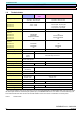
TECHNICAL DESCRIPTION MICROMASTER MICROMASTER Vector MIDIMASTER Vector 2.5 200 5 Frequency (Hz) Constant current range Constant current + orientation range Fully-orientated Vector control The above diagram illustrates the operating ranges of the MICRO/MIDIMASTER Vector sensorless vector control. Whereby the frequency range of the vector control lies between 5Hz and 200Hz; V/Hz control is automatically selected for values outside this range.
TECHNICAL DESCRIPTION MICROMASTER MICROMASTER Vector MIDIMASTER Vector 2.1.10 MICROMASTER and MICRO/MIDIMASTER Vector (in the V/Hz mode) V/Hz control for single and multi-motor drives with asynchronous motors where there are no special requirements placed on dynamic response. This is the case, for example, for pumps and fans and basic drives for slides.
TECHNICAL DESCRIPTION MICROMASTER MICROMASTER Vector MIDIMASTER Vector 2.1.12 MICRO/MIDIMASTER Vector (sensorless vector control) This control type is preferably used for single drives with asynchronous motors where the requirements placed on the dynamic response range from low to high, and for speed control ranges up to 1:10. It is suitable for most industrial applications, for example, extruders, packaging machines, industrial washing machines, lifts and cranes.
TECHNICAL DESCRIPTION MICROMASTER MICROMASTER Vector MIDIMASTER Vector 2.1.13.1 Features of different control techniques Mode V/Hz Digital setpoint resolution 0.01 Analog setpoint resolution 10 bit Internal frequency resolution 0.
TECHNICAL DESCRIPTION MICROMASTER MICROMASTER Vector MIDIMASTER Vector 2.3 causes the motor to be quickly braked and in a controlled fashion. The energy fed back into the DC link is converted into thermal energy by the motor using the integrated braking chopper (P070 / P075) and an external braking resistor for MICROMASTER Vector or using the external brake module (EBU) and external braking resistor options for MIDIMASTER Vector.
TECHNICAL DESCRIPTION MICROMASTER MICROMASTER Vector MIDIMASTER Vector 2.
ENGINEERING INFORMATION AND INSTRUCTIONS MICROMASTER MICROMASTER Vector MIDIMASTER Vector 3. Engineering information and instructions 3.1 Technical comparison table 3/1 3.2 Dimensions and weights 3/2 3.3 Degrees of protection 3/5 3.4 Design guidelines 3/6 3.5 Line supply 3/7 3.6 Control connections 3/8 3.7 Recommended cable cross-sections 3/11 3.8 Maximum motor cable lengths 3/13 3.9 De-rating 3/15 3.10 Selection help for motors 3/17 3.
ENGINEERING INFORMATION AND INSTRUCTIONS MICROMASTER MICROMASTER Vector MIDIMASTER Vector > empty page < SIEMENS DA 64 – 2002/2003 3/1 Version D
ENGINEERING INFORMATION AND INSTRUCTIONS MICROMASTER MICROMASTER Vector MIDIMASTER Vector 3.1 Technical comparison table Power range Voltage range MICROMASTER 6SE92 MICROMASTER Vector 6SE32 MIDIMASTER Vector 6SE32 120 W - 3 kW, 230 V, 1 AC 120 W - 4 kW, 230 V, 3 AC 370 W – 7.5 kW, 400 V, 3 AC 208 - 240 V +/-10 % 380 - 500 V +/-10 % 120 W - 3 kW, 230 V, 1 AC 120 W - 4 kW, 230 V, 3 AC 370 W – 7.5 kW, 400 V, 3 AC 208 - 240 V +/-10 % 380 - 500 V +/-10 % 5.
ENGINEERING INFORMATION AND INSTRUCTIONS MICROMASTER MICROMASTER Vector MIDIMASTER Vector 3.2 Dimensions and weights B MICROMASTER und MICROMASTER Vector inverters must be mounted to a suitable, flat surface using bolts, washers and nuts. F DIN rail H1 H A H1 H Æ Depth D Two bolts are required for Size A drive units. (M4) Æ = 4.5 mm T B Four bolts are required for Size B drive units. (M4) 2 bolts M4 2 nuts M4 2 washers M4 Size A Four bolts are required for Size C drive units.
ENGINEERING INFORMATION AND INSTRUCTIONS MICROMASTER MICROMASTER Vector MIDIMASTER Vector B B1 H1 H DepthD H Æ Æ = 8,5mm B T 4 bolts M8 4 nuts M8 4 washers M8 Housingsizes4, 5and6 MIDIMASTER Vector – sizes 4, 5 and 6 Standard version: IP21 Version with integrated filter: IP20 B B1 H1 H DepthD H Æ Æ = 8,5mm B 6 bolts M8 6 nuts M8 6 washers M8 Housingsize7 T MIDIMASTER Vector - size 7 Standard version: Version with integrated filter: IP21 IP20 W1 H1 H Depth D Æ Æ = 8.
ENGINEERING INFORMATION AND INSTRUCTIONS MICROMASTER MICROMASTER Vector MIDIMASTER Vector MIDIMASTER Vector Table 2: Size Type 3-ph. 208 – 240 V AC 3-ph. 400 – 500 V AC MDV220/4 MDV400/4 MDV550/2 MDV550/4 MDV750/2 MDV750/3 MDV750/4 MDV1100/2 MDV1100/3 MDV1100/4 MDV1500/2 MDV1500/3 MDV1500/4 MDV1850/2 MDV1850/3 MDV1850/4 MDV2200/2 MDV2200/3 MDV2200/4 MDV3000/2 MDV3000/3 MDV3000/4 MDV3700/2 MDV3700/3 MDV3700/4 MDV4500/2 MDV4500/3 MDV5500/3 MDV7500/3 4 5 5 6 6 6 7 7 7 - 4 4 5 5 6 6 6 7 7 7 3-ph.
ENGINEERING INFORMATION AND INSTRUCTIONS MICROMASTER MICROMASTER Vector MIDIMASTER Vector 3.3 Degrees of protection The IP number defines the degree of protection against the ingress of dirt, foreign bodies, water etc. (Ingress Protection; IP) for the associated drive inverter.
ENGINEERING INFORMATION AND INSTRUCTIONS MICROMASTER MICROMASTER Vector MIDIMASTER Vector Supply Separate filter Metal mounting plate Retain the motor and control cables to the metal plate using suitable clamps . 3.4 Mounting and installation guidelines Fig. 3.11.3 Wiring guidelines to optimize the noise immunity of MICROMASTER and MICROMASTER Vector, Size C The drive inverters are designed for use in industrial environments with strong electromagnetic noise and disturbances.
ENGINEERING INFORMATION AND INSTRUCTIONS MICROMASTER MICROMASTER Vector MIDIMASTER Vector 3.5 Line supply The drive inverters are designed for limit values defined in the following standards. These standards describe the noise voltages permissible at the line supply input.
ENGINEERING INFORMATION AND INSTRUCTIONS MICROMASTER MICROMASTER Vector MIDIMASTER Vector 3.6 Control connections MICROMASTER: PE 1/3-ph. 230 V AC 3-ph. 380 - 500 V AC ³ 4,7 k W V: 0 - 10 V 2 - 10 V or AIN+ AIN- L/L1, N/L2 or L/L1, N/L2, L3 PE +10 V 1 SI 0V 2 3 AD 4 ~ Jog P – 24 V + RS485 DIN1 DIN2 5 DIN3 6 or 7 Power supply for actual value sensing or another load CPU +15 V 8 0V 9 RL1 RL1B 10 RL1C 11 3 PE ~ U, V, W M Output relay (NO contact) max. 0.
ENGINEERING INFORMATION AND INSTRUCTIONS MICROMASTER MICROMASTER Vector MIDIMASTER Vector MICROMASTER Vector & MIDIMASTER Vector 8 PE 3-ph. 208 - 230 V AC 3-ph. 380 - 500 V AC 3-ph. 525 - 575 V AC ³4.
ENGINEERING INFORMATION AND INSTRUCTIONS MICROMASTER MICROMASTER Vector MIDIMASTER Vector MICROMASTER Vector & MIDIMASTER Vector Output relay max. 2,0 A/110 V AC 0.8 A/ 240 V AC( overvoltage Cat. 2 ) or 2 A/ 30 V DC (ohmic load) P10+ 1 0 V AEIN+ AEIN- DEIN1 DEIN2 DEIN3 DEIN4 P15+PIDEIN+ PIDEIN- 2 3 4 5 6 7 8 9 10 11 AAUS+ AAUS- PTC 12 13 14 PTC DEIN5 DEIN6 15 16 17 18 19 21 20 22 RL1A RL1B RL1C RL2B RL2C (NC) (NO) (COM) (NO) (COM) Power supply (+10 V, max.
ENGINEERING INFORMATION AND INSTRUCTIONS MICROMASTER MICROMASTER Vector MIDIMASTER Vector 3.7 Recommended cable cross-sections MICROMASTER Vector MICROMASTER Basic MMV12; MMV25; MMV37 MMV55; MMV75 MMV110; MMV150; MMV220 MMV300 MM12; MM25; MM37; MM55; MM75 MM110; MM150; MM220 Recommended cable crosssection, line side 1.0 mm² 1.5 mm² 2.5 mm² MM300 4.0 mm² 2.5 mm² 4.0 mm² MMV12/2; MMV25/2; MMV37/2 MMV55/2; MMV75/2 MMV110/2 MMV150/2 MMV220/2; MMV300/2 MM12/2; MM25/2; MM37/2; MM55/2; MM75/2 1.
ENGINEERING INFORMATION AND INSTRUCTIONS MICROMASTER MICROMASTER Vector MIDIMASTER Vector MIDIMASTER Vector Torque application MDV550/2 MDV550/2 MDV750/2 MDV750/2 MDV1100/2 MDV1100/2 MDV1500/2 MDV1500/2 MDV1850/2 MDV1850/2 MDV2200/2 MDV2200/2 MDV3000/2 MDV3000/2 MDV3700/2 MDV3700/2 MDV4500/2 MDV4500/2 Constant torque (CT) Variable torque (VT) Constant torque (CT) Variable torque (VT) Constant torque (CT) Variable torque (VT) Constant torque (CT) Variable torque (VT) Constant torque (CT) Variable torque
ENGINEERING INFORMATION AND INSTRUCTIONS MICROMASTER MICROMASTER Vector MIDIMASTER Vector MIDIMASTER Vector Torque application MDV220/4 MDV220/4 MDV400/4 MDV400/4 MDV550/4 MDV550/4 MDV750/4 MDV750/4 MDV1100/4 MDV1100/4 MDV1500/4 MDV1500/4 MDV1850/4 MDV1850/4 MDV2200/4 MDV2200/4 MDV3000/4 MDV3000/4 MDV3700/4 MDV3700/4 Constant torque (CT) Variable torque (VT) Constant torque (CT) Variable torque (VT) Constant torque (CT) Variable torque (VT) Constant torque (CT) Variable torque (VT) Constant torque (CT)
ENGINEERING INFORMATION AND INSTRUCTIONS MICROMASTER MICROMASTER Vector MIDIMASTER Vector 3.8 Max. motor cable lengths Drive inverter power Rated voltage KW Housing size V Without output reactor With output reactor Nonshielded cable M Non-shielded cable M Shielded cable m Shielded cable m MICROMASTER / MICROMASTER Vector 0.12 - 1.5 208-240 ±10% A, B 200 200 250 225 2.2 – 4.0 208-240 ±10% C 185 150 235 185 0.37 - 1.5 380-500 ± 10% A 110 80 185 125 2.2 – 3.
ENGINEERING INFORMATION AND INSTRUCTIONS MICROMASTER MICROMASTER Vector MIDIMASTER Vector 3.9 De-rating Voltage and current de-rating for high installation altitudes Permissible supply voltage as a % of the rated voltage Permissible current as a % of the rated current 100 100 90 90 80 80 70 70 60 60 1000 4000 2000 3000 500 Installation altitude in m above sea level 2000 3000 1000 4000 500 Installation altitude in m above sea level Max.
ENGINEERING INFORMATION AND INSTRUCTIONS MICROMASTER MICROMASTER Vector MIDIMASTER Vector Maximum output current referred to the pulse frequency As a result of higher switching losses at increased switching frequencies, the maximum continuous current (100 %) of some drive inverters can be reduced, if a pulse frequency other than the standard pulse frequency is selected. Type Note: Perm. load as a % of the max.
ENGINEERING INFORMATION AND INSTRUCTIONS MICROMASTER MICROMASTER Vector MIDIMASTER Vector 3.
ENGINEERING INFORMATION AND INSTRUCTIONS MICROMASTER MICROMASTER Vector MIDIMASTER Vector Motor protection: MICROMASTER Vector and MIDIMASTER Vector: The motors are protected using a PTC thermistor. This is connected to the drive inverter control terminals. The motor protection function is activated using the parameter P087 = 1; for a motor fault ("Low signal" at the control input), error code F004 is displayed.
ENGINEERING INFORMATION AND INSTRUCTIONS MICROMASTER MICROMASTER Vector MIDIMASTER Vector When selecting the output reactors, the max. output frequency and the max. pulse frequency should be taken into account. It is not possible to use sinusoidal or dv/dt filters from the MASTERDRIVE 6SE70... series for applications with MICROMASTER / MIDIMASTER. The reasons are technical ones (the filters are matched to the pulse frequency and modulation of the MASTERDRIVE series).
ENGINEERING INFORMATION AND INSTRUCTIONS MICROMASTER MICROMASTER Vector MIDIMASTER Vector 3.11 Maintaining the EMC Directives Since January 1996, all manufacturers/companies assembling electrical equipment which have an autonomous function and which are offered to end users as a single unit, must fulfill the EMC Directive 89/336/EC. Manufacturers/companies assembling electrical equipment can prove this conformance in three different ways: 1.
ENGINEERING INFORMATION AND INSTRUCTIONS MICROMASTER MICROMASTER Vector MIDIMASTER Vector Class 2: Filtered industrial environments For this level, manufacturers/companies assembling electrical equipment can themselves certify that their equipment is in conformance with the EMC Directive for industrial environments referred to the EMC characteristics of the motor drive system.
ENGINEERING INFORMATION AND INSTRUCTIONS MICROMASTER MICROMASTER Vector MIDIMASTER Vector 3.12 Technical data for line and output filter 6SE3290-0BA87-0FB0 Radio interference suppression filter, Class B; 1-ph.; 208V – 240 V AC+/-10%; 3A; 50/60Hz 6SE3290-0BA87-0FB2 Radio interference suppression filter, Class B; 1-ph.; 208V – 240 V AC+/-10%; 10A; 50/60Hz Housing dimensions are valid for both filters 174 2 Terminal 2.5mm Nominal torque for the screws 0.7 Nm Rating plate ± 0. 4 4 holes, Æ 4.
ENGINEERING INFORMATION AND INSTRUCTIONS MICROMASTER MICROMASTER Vector MIDIMASTER Vector 6SE3290-0DA87-0FA1 Radio interference suppression filter, Class A; 3-ph.; 208V – 460V AC+/-10%; 6A; 50/60Hz 6SE3290-0DA87-0FB1 Radio interference suppression filter, Class B; 3-ph.; 208V – 460V AC+/-10%; 6A; 50/60Hz Housing dimensions are valid for both filters 174 Terminal 2.5mm2 Nominal torque for the screws 0.7 Nm Rating plate ± 0.4 160 4 holes Æ 4.8 mm green/yellow Grounding stud, M4 Nominal torque 1.
ENGINEERING INFORMATION AND INSTRUCTIONS MICROMASTER MICROMASTER Vector MIDIMASTER Vector 6SE3290-0BB87-0FB4 Radio interference suppression filter, Class B; 1-ph.; 208V – 240V AC+/-10% +/-10%; 22A; 50/60Hz Terminal 4 mm 2 Nominal torque 1.5 Nm Rating plate Grounding stud, M4 Nominal torque 1.5 Nm 4 holes Æ 4.8 mm 4 mounting holes f. the drive inv. M4 ( max. 5 mm thread depth) max. torque 1.5 Nm Transition element Fork-type cable lug, length 3.5 mm inner conductor terminal diameter, 3.
ENGINEERING INFORMATION AND INSTRUCTIONS MICROMASTER MICROMASTER Vector MIDIMASTER Vector 6SE3290-0DB87-0FA3 Radio interference suppression filter, Class A; 3-ph.; 208V – 480V AC+/-10%; 12A; 50/60Hz 6SE3290-0DB87-0FB3 Radio interference suppression filter, Class B; 3-ph.; 208V – 480V AC+/-10%; 12A; 50/60Hz Terminal 2.5mm² Nominal torque of the screws 0.7 Nm Rating plate 4 holes Æ 4.8 mm Grounding stud, M4 Nominal torque 1.5 Nm Transition element 4 mounting holes f. the drive inv. M4 ( max.
ENGINEERING INFORMATION AND INSTRUCTIONS MICROMASTER MICROMASTER Vector MIDIMASTER Vector 6SE3290-0BC87-0FB4 Radio interference suppression filter, Class B; 1-ph.; 208V – 240V AC+/-10%; 32A; 50/60Hz Term. 4 mm² Nominal torque 1.5 Nm Rating plate Grounding stud, M4 Nominal torque 1.5 N 4 holes Æ 5.8 mm 4 mounting holes f. the drive inverter (max. 5 mm therad depth) max. torque, 1.5 Nm Transition element Fork-type cable lug, length 3.5 mm inner conductor terminal diameter 3.
ENGINEERING INFORMATION AND INSTRUCTIONS MICROMASTER MICROMASTER Vector MIDIMASTER Vector 6SE3290-0DC87-0FA4 Radio interference suppression filter, Class A; 3-ph.; 208V – 480V AC+/-10%; 25A; 50/60Hz 6SE3290-0DC87-0FB4 Radio interference suppression filter, Class B; 3-ph.; 208V – 480V AC+/-10%; 25A; 50/60Hz Terminal 4 mm² Nominal torque of the screws 1.5 Nm Rating plate Grounding stud, M4 Nominal torque 1.5 Nm 4 holes Æ 5.8 mm Transition element 4 mounting holes f. the drive inverter M5 (max.
ENGINEERING INFORMATION AND INSTRUCTIONS MICROMASTER MICROMASTER Vector MIDIMASTER Vector 6SE3290-0DG87-0FA5 Radio interference suppression filter, Class A; 3-ph.
ENGINEERING INFORMATION AND INSTRUCTIONS MICROMASTER MICROMASTER Vector MIDIMASTER Vector 6SE3290-0DH87-0FA5 Radio interference suppression filter, Class A; 3-ph.
ENGINEERING INFORMATION AND INSTRUCTIONS MICROMASTER MICROMASTER Vector MIDIMASTER Vector 6SE3290-0DJ87-0FA6 Radio interference suppression filter, Class A; 3-ph.
ENGINEERING INFORMATION AND INSTRUCTIONS MICROMASTER MICROMASTER Vector MIDIMASTER Vector 6SE3290-0DK87-0FA7 Radio interference suppression filter, Class A; 3-ph.; 208V – 460V AC+/-10%; 180A; 50/60Hz 6SE3290-0DK87-0FB7 Radio interference suppression filter, Class B; 3-ph.
ENGINEERING INFORMATION AND INSTRUCTIONS MICROMASTER MICROMASTER Vector MIDIMASTER Vector 6SE2100-1FC20 EMC input filter, Class B Radio interference suppression filter, Class B; 3-ph.; 208V – 460V AC+/-10%; 38A; 50/60Hz 1 9 . x a m DA64-5005 M6 connecting bolts max.125.8 max. 281 max. 231 115 Labeling 6.6 L1 L2 L3 PE Supply Load 2 0 4 1 L1 L2 L3 PE 6 5 1 .x a m 10mm connecting terminals 6SE2100-1FC21 EMC input filter, Class B max.141 Radio interference suppression filter, Class B; 3-ph.
ENGINEERING INFORMATION AND INSTRUCTIONS MICROMASTER MICROMASTER Vector MIDIMASTER Vector dV/dt output filter (MASTER DRIVES series) Sizes E dV/dt output filter, Sizes B and C D c c 1) e H H f b a 1) W D a 1) d d b f W dV/dt output filter Size H [mm] W [mm] D [mm] a [mm] b [mm] c [mm] d [mm] f [mm] Weight, approx. [kg] 1) B 425 135 350 67.
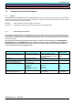
ENGINEERING INFORMATION AND INSTRUCTIONS MICROMASTER MICROMASTER Vector MIDIMASTER Vector 3.13 Line supply harmonics and line supply impedance Line supply harmonics In operation, the drive inverter causes non-sinusoidal line currents with harmonics. These harmonic currents can be reduced by using line reactors. Line impedance The ratio between the rated drive power / system fault level should not fall below 1 %.
ENGINEERING INFORMATION AND INSTRUCTIONS MICROMASTER MICROMASTER Vector MIDIMASTER Vector Calculating a line reactor using an example.
ENGINEERING INFORMATION AND INSTRUCTIONS MICROMASTER MICROMASTER Vector MIDIMASTER Vector 3.14 Technical data & dimensions for line reactors & output reactors Line reactors, MICROMASTER Order No. [MRPD] Enclosure size Current Voltage Weight 6SE6400-3CC00-4AB0 FSA 4A 1-ph. 200V - 240V AC+/-10% 0.5Kg 6SE6400-3CC01-0AB0 FSA 10A 1-ph. 200V - 240V AC+/-10% 0.6Kg 6SE6400-3CC00-3AC0 FSA 3A 3-ph. 200V - 240V AC+/-10% 0.6Kg 6SE6400-3CC00-2AD0 FSA 2A 3-ph. 200V - 240V AC+/-10% 0.
ENGINEERING INFORMATION AND INSTRUCTIONS MICROMASTER MICROMASTER Vector MIDIMASTER Vector MICROMASTER output reactors ** Order No. [MRPD] Enclosure size Current Voltage Weight 6SE6400-3TC00-4AD0 FSA 4A 3-ph. 200V - 480V AC+/-10% 0.8Kg 6SE6400-3TC01-0BD0 FSB 10A 3-ph. 200V - 480V AC+/-10% 3.4Kg 6SE3200-3TC03-2CD0 FSC 32A 3-ph. 200V - 480V AC+/-10% 5.6Kg Dimensions for 6SE...
ENGINEERING INFORMATION AND INSTRUCTIONS MICROMASTER MICROMASTER Vector MIDIMASTER Vector Schematic diagram of the 6SE...
ENGINEERING INFORMATION AND INSTRUCTIONS MICROMASTER MICROMASTER Vector MIDIMASTER Vector Technical data for line reactors 4E... Please refer to Catalog PD30 2001 for more details 3-phase line supply reactors 4EM... dimensions with terminals for any reactor arrangement ILn up to 40A Mounting holes Type 4EM46 4EM47 4EM48 4EM49 4EM50 4EM51 4EM52 4EM61 Rated AC currents ILn To 40 A To 40 A To 40 A To 40 A To 40 A To 40 A To 40 A To 40 A b1 d1 All dimensions in mm 51 3.6 60 4.8 69 4.8 85 4.8 97 5.
ENGINEERING INFORMATION AND INSTRUCTIONS MICROMASTER MICROMASTER Vector MIDIMASTER Vector 3-phase line supply reactors 4EP... dimensions with terminals for any reactor arrangement ILn = 35.5 A n4 n2 d1 n1 n3 d3 e h l1 d2 d1 1) n2 n1 n4 l2 n3 b1 Three-phase line reactor Type 4EP32 4EP33 4EP34 4EP35 4EP36 4EP37 4EP38 4EP39 4EP40 b1 max . mm 57.5 64 73 68 78 73 88 99 119 d1 D2 mm Mm 4.8 4.8 4.8 4.8 4.8 5.8 5.
ENGINEERING INFORMATION AND INSTRUCTIONS MICROMASTER MICROMASTER Vector MIDIMASTER Vector 3-phase line supply reactors 4EP... dimensions with terminals for any reactor arrangement ILn 36 A to 50 A n4 n2 h n1 n3 d3 e l1 d1 d2 n2 n1 n3 and n4 mounting holes according to EN 60852-4 n4 n3 n1 and n2 mounting holes according to DIN 41308 l2 b1 Three-phase line reactor b1 d1 D2 d3 e Type max . mm max. mm Mm mm mm 4EP38 4EP39 4EP40 88 99 119 5.8 7 7 11 13 13 M5 M6 M6 86 91.5 101.
ENGINEERING INFORMATION AND INSTRUCTIONS MICROMASTER MICROMASTER Vector MIDIMASTER Vector 3-phase line supply reactors 4EP... dimensions with flat connector for any reactor arrangement ILn = 51 A n4 n2 e h l1 d1 d3 n1 n3 d2 n2 n1 n3 and n4 mounting holes according to EN 60852-4 n4 n3 n1 and n2 mounting holes according to DIN 41308 l2 b1 Three-phase line reactor b1 d1 max . mm mm d2 d3 H l1 l2 N1 n2 Max max. max. ±IT12 ±IT12 . Mm mm mm Mm mm n3 ±IT12 n4 ±IT12 mm e max .
ENGINEERING INFORMATION AND INSTRUCTIONS MICROMASTER MICROMASTER Vector MIDIMASTER Vector Three-phase line reactors 4EU... dimensions with flat connectors, for mounting reactors onto horizontal surfaces l4 e d3 n4 h l1 n2 M6 n2 n1 b1 l2 Three-phase line reactor Type 4EU24 4EU25 4EU27 4EU30 4EU36 4EU39 4EU43 4EU45 4EU47 4EU50 4EU52 Mounting holes b1 max . mm 104 128 146 155 169 174 194 221 251 195 220 d1 D2 mm Mm l4 l2 l1 H e max Max max max max . . . . .
ENGINEERING INFORMATION AND INSTRUCTIONS MICROMASTER MICROMASTER Vector MIDIMASTER Vector MIDIMASTER output reactors** Order No. [MRPD] Enclosure size Current Voltage Weight 4EP3700-5DS FS4 50A 3.3Kg MDV550/2 6SE6400-3TC02-8DC0 FS4 28A 1.3Kg MDV750/2 6SE6400-3TC05-4DD0 FS5 54A 6SE6400-3TC08-0ED0 FS6 80A 6SE6400-3TC15-4FD0 FS7 154A 6SE7022-2FS87-1FE0*** FS4 25.
ENGINEERING INFORMATION AND INSTRUCTIONS MICROMASTER MICROMASTER Vector MIDIMASTER Vector Schematic diagram, output reactor 6SE...
ENGINEERING INFORMATION AND INSTRUCTIONS MICROMASTER MICROMASTER Vector MIDIMASTER Vector Schematic diagram, output reactor 6SE...
ENGINEERING INFORMATION AND INSTRUCTIONS MICROMASTER MICROMASTER Vector MIDIMASTER Vector 3.15 MICROMASTER Vector braking resistors 1 m, 2 core shielded cable with 6.3 mm Faston connectors 1 m, 2 core shielded cable with 6.3 mm Faston connectors These braking resistors are used with the MICROMASTER Vector drive inverters. They enable high inertia loads to be quickly decelerated.
ENGINEERING INFORMATION AND INSTRUCTIONS MICROMASTER MICROMASTER Vector MIDIMASTER Vector 3.16 Electronic braking module (EBU) and braking resistors for MIDIMASTER Vector The kinetic energy of the motor and load is fed back into the drive inverter when using the optional electronic braking module (EBU) and braking resistor. It is then converted into heat in the external braking resistors which significantly improves the braking effect.
ENGINEERING INFORMATION AND INSTRUCTIONS MICROMASTER MICROMASTER Vector MIDIMASTER Vector Permissible load for intermittent duty 100% Fig. 4 - Cycle diagram for the electronic braking module 50% Permissible load for continuous duty 10% 5 10 15 20 Resistor type Dimensions L x W x D (mm) MIDIMASTER Vector line supply voltage (V) Resistance (W) Surge power (kW) Average power (kW) Order No.
ENGINEERING INFORMATION AND INSTRUCTIONS MICROMASTER MICROMASTER Vector MIDIMASTER Vector Braking power for drive inverters with line supply voltages 3-ph. 208 V to 240 V AC Drive inverter Rated drive inverter power Type MDV550/2 kW 5.5 MDV750/2 7.5 MDV1100/2 11 MDV1500/2 15 MDV1850/2 18.5 MDV2200/2 22 MDV3000/2 30 MDV3700/2 37 MDV4500/2 45 Braking power (min.
Communications / interfaces MICROMASTER MICROMASTER Vector MIDIMASTER Vector 4. Communications & interfaces 4/1 4.1 Communications, operator control and display elements 4/1 4.2 Standard operator panel 4/1 4.3 Serial RS485 interface 4/1 4.4 Control terminal strips 4/3 4.5 OPM2 plain text operator panel 4/3 4.6 CB15 PROFIBUS module 4/4 4.7 CB16 CAN bus module 4/7 4.8 AS-Interface module 4/7 4.9 DRIVE-MONITOR and DriveES commissioning tool 4/7 4.
Communications / interfaces MICROMASTER MICROMASTER Vector MIDIMASTER Vector > empty page < SIEMENS DA 64 – 2001/2002 4/1 Version C4
Communications / interfaces MICROMASTER MICROMASTER Vector MIDIMASTER Vector 4. LED display COMMUNICATIONS & INTERFACES JOG key Key, CLOCKW ISE/ COUNTER-CLOCKWISE direction of rotation ON key 4.1 Communications, operator control and display elements MICROMASTER, MICROMASTER Vector and MIDIMASTER Vector have the identical operator control and display elements. The AC drive inverters can either be controlled, data read-out and parameterized at the unit itself or also externally: 1.
Communications / interfaces MICROMASTER MICROMASTER Vector MIDIMASTER Vector Pin 1 2 3 4 5 6 7 8 9 Function, information Not assigned Not assigned RS485 send and receive data line, two-wire, positive differential input/output B/P Not assigned Reference potential, 0V 5V/250mA power supply Not assigned RS485 send and receive data line, two-wire, negative differential input/output A/N Not assigned Table 1: Pin assignment of the SUB-D connector Notes: 1.
COMMUNICATIONS / INTERFACES MICROMASTER MICROMASTER Vector MIDIMASTER Vector The operator panel is automatically activated as soon as it is connected to a drive inverter or the voltage is switched-on. Dimensions H x W x D Current drain at 5 V Degree of protection Max. cable length Table 2: 130 mm x 73 mm x 40 mm 200 mA IP 54 5m Drives connected to the USS bus, in this case 0, 7 and 16 can be selected using the arrow keys M RUNNING F=50.00Hz Technical data LCD display P000 RUNNING ® RPM=1250 F=50.
COMMUNICATIONS / INTERFACES MICROMASTER MICROMASTER Vector MIDIMASTER Vector The power supply specifications are as follows: Voltage tolerance 6V ± 0.5V Current drain for operation with a drive inverter: 50mA, Current drain for operation without drive inverter: 250mA The advantages of the automation of a system using PROFIBUS-DP are listed in the following: · Only one single network for operator panels, drives, sensors, actuators, PLCs. · Cost saving when it comes to the installation time and wiring.
COMMUNICATIONS / INTERFACES MICROMASTER MICROMASTER Vector MIDIMASTER Vector 5 Multi-mode operation is possible: Control data can be input via the terminal strip (digital inputs) and setpoints via the serial bus. Alternatively, the setpoint can be received from a local source (analog input), whereby the drive is controlled via the serial bus. · 9 4 8 3 7 All of the drive parameters are accessible via the serial connecting cable.
COMMUNICATIONS / INTERFACES MICROMASTER MICROMASTER Vector MIDIMASTER Vector A segment can be extended by using RS485 amplifiers. Recommended: SINEC L2 amplifier for RS 485 (Order No.: 6ES7972-0AA00-0XA0). In order to guarantee reliable operation of the serial bus system, the cable must be terminated at both ends using terminating resistors.
COMMUNICATIONS / INTERFACES MICROMASTER MICROMASTER Vector MIDIMASTER Vector 4.7 CAN bus module CB16 · The CAN bus module was developed for operation with MICROMASTER Vector / MIDIMASTER Vector and · supports the CAN Open protocol. It fulfills the requirements of the CAN specification DS402. All of the drive inverter parameters are accessible via the bus. There are no restrictions regarding the parameters harmonized in the DS402 specification.
COMMUNICATIONS / INTERFACES MICROMASTER MICROMASTER Vector MIDIMASTER Vector 4.10 Diagnostic functions, fault codes and parameter list The MICROMASTER, MICROMASTER Vector and MIDIMASTER Vector drive inverters have two alarm function stages: Warnings and Faults. 1. Warnings The first stage implies a warning which is output if a drive inverter operating parameter reaches its limit value. These parameters can include, for example, current, voltage or temperature.
COMMUNICATIONS / INTERFACES MICROMASTER MICROMASTER Vector MIDIMASTER Vector 4.11 Table of the fault and alarm codes Fault message Text 6SE32... 6SE92... F001 Overvoltage X X Alarm Text F002 Overcurrent X F003 Overload X F004 Overtemperature, motor X F005 Overtemperature, drive inverter X X F008 USS protocol time out X X F009 Undervoltage X 6SE32... 6SE92...
COMMUNICATIONS / INTERFACES MICROMASTER MICROMASTER Vector MIDIMASTER Vector 4.12 Parameter list Legend: • = These parameters can also be changed while the drive inverter is operational. ²²² = The setting value depends on the drive inverter type. Parameter Function Range [factory setting] MICROMASTER MICRO/MIDIMASTER Vector P000 Operating display - - P001 • Display mode 0 - 8 [0] 0 - 9 [0] P002 • Ramp-up time (seconds) 0 – 650.0 [10.0] 0 – 650.0 [10.
COMMUNICATIONS / INTERFACES MICROMASTER MICROMASTER Vector MIDIMASTER Vector Parameter Function Range [factory setting] MICROMASTER MICRO/MIDIMASTER Vector P045 Inversion fixed setpoints for fixed frequencies 1 - 4 0 - 7 [0] 0 - 7 [0] P046 Fixed frequency 5 (Hz) 0.00 - 400.00 [25.00] 0.00 - 650.00 [25.00] P047 Fixed frequency 6 (Hz) 0.00 - 400.00 [30.00] 0.00 - 650.00 [35.00] P048 Fixed frequency 7 (Hz) 0.00 - 400.00 [35.00] 0.00 - 650.00 [40.00] P049 Fixed frequency 8 (Hz) - 0.
COMMUNICATIONS / INTERFACES MICROMASTER MICROMASTER Vector MIDIMASTER Vector Parameter Function P087 • Motor PTC enable Range [factory setting] MICROMASTER MICRO/MIDIMASTER Vector - 0 - 1 [0] P088 Automatic calibration - 0 - 1 [1] P089 • Stator resistance (Ω) 0.01 - 100.00 [²²²] 0.01 - 199.
COMMUNICATIONS / INTERFACES MICROMASTER MICROMASTER Vector MIDIMASTER Vector Parameter Function Range [factory setting] MICROMASTER MICRO/MIDIMASTER Vector P212 • 100 % setpoint 0.00 - 100.00 [100.00] 0.00 - 100.00 [100.00] P220 Frequency cut-off 0 - 1 [0] 0 - 1 [0] P321 Minimum analog frequency for analog setpoint 2 - 0.00 - 650.00 [0.00] P322 • Maximum analog frequency for analog setpoint 2 - 0.00 - 650.00 [0.
COMMUNICATIONS / INTERFACES MICROMASTER MICROMASTER Vector MIDIMASTER Vector > empty page < SIEMENS DA 64 – 2001/2002 4/15 Version C3
DRIVE INVERTER SELECTION & ORDERING DATA MICROMASTER MICROMASTER Vector MIDIMASTER Vector 5 Drive inverter selection & ordering data 5.1 MICROMASTER/MICROMASTER Vector 5/1 5.
DRIVE INVERTER SELECTION & ORDERING DATA MICROMASTER MICROMASTER Vector MIDIMASTER Vector > empty page < SIEMENS DA 64 – 2002/2003 5/1 Version D
DRIVE INVERTER SELECTION & ORDERING DATA MICROMASTER MICROMASTER Vector MIDIMASTER Vector 5.1 MICROMASTER/MICROMASTER Vector MICROMASTER / MICROMASTER Vector, 1-ph. 208V - 240V AC±10%, with integrated filter IP20 (NEMA 1) MICROMASTER MICROMASTER Vector Rated motor power Rated output current Maximum continuous output current Input current Dimensions Weight MICROMASTER (approx.) MICROMASTER Vector HxW xD Type Type kW A A A mm kg Order No. Order No. MM12 MMV12 0.12 0.75 0.9 1.
DRIVE INVERTER SELECTION & ORDERING DATA MICROMASTER MICROMASTER Vector MIDIMASTER Vector MICROMASTER/MICROMASTER Vector, 3-ph. 380V - 500V AC±10%, without filter IP20 (NEMA 1) Drive inverter MICROMASTER Type MICROMASTER Vector Type MM37/3 Rated motor power Rated output current Maximum Input continuous output current current Dimensions Weight (approx.) Drive inverter HxW xD 400 V 500 V 400 V 500 V MICROMASTER MICROMASTER Vector kW A A A A A mm kg Order No. Order No. MMV37/3 0.
DRIVE INVERTER SELECTION & ORDERING DATA MICROMASTER MICROMASTER Vector MIDIMASTER Vector 5.2 MIDIMASTER Vector MIDIMASTER Vector, 3-ph. 208 V -- 240 V AC±10%, without filter IP21 (NEMA 1) Drive inverter Rated output current at 1) 2) M ~ n² Input current Type A A A kW hp kW hp mm kg Order No. MDV550/2 22 28 32 5.5 7.5 7.5 10 450x275x210 11 6SE3222-3CG40 (max. cont. current) Rated motor output at Rated motor output at M = const. M ~ n² Dimensions Weight approx.
DRIVE INVERTER SELECTION & ORDERING DATA MICROMASTER MICROMASTER Vector MIDIMASTER Vector MIDIMASTER Vector, 3-ph. 208 V - 240 V AC±10%, with integrated filter, Class A, IP20 (NEMA 1) Drive inverter Rated output current at 1) 2) M ~ n² Input current Type A A A kW hp kW hp mm kg Order No. MDV550/2 22 28 32 5.5 7.5 7.5 10 700x275x210 18 6SE3222-3CG50 (max. cont. current) Rated motor output at Rated motor output at M = const. M ~ n² Dimensions Weight approx.
DRIVE INVERTER SELECTION & ORDERING DATA MICROMASTER MICROMASTER Vector MIDIMASTER Vector MIDIMASTER Vector, 3-ph. 208 – 240V AC±10%, without filter IP56 (NEMA 4/12) Drive inverter Rated output current at 2) M = const. Rated output current at 1) 2) M ~ n² Input current Type A A A kW hp kW hp mm kg Order No. MDV550/2 22 28 32 5.5 7.5 7.5 10 675x360x351 30 6SE3222-3CS45 (max. cont. current) Rated motor output at Rated motor output at M = const.
DRIVE INVERTER SELECTION & ORDERING DATA MICROMASTER MICROMASTER Vector MIDIMASTER Vector MIDIMASTER Vector, 3-ph. 525 – 575V AC±15%, without filter IP56 (NEMA 4/12) Drive inverter Rated output current at 2) M = const. Rated output current at 1) 2) M ~ n² Input current Type A A A kW hp kW hp mm kg Order No. MDV220/4 3.9 6.1 7 2.2 3 4 5 675x360x351 28 6SE3213-8FS45 MDV400/4 6.1 9 10 4 5 5.5 7.5 675x360x351 29 6SE3216-1FS45 MDV550/4 9 11 12 5.5 7.5 7.
OPTIONS MICROMASTER MICROMASTER Vector MIDIMASTER Vector 6 Options 6.1 Overview of the options 6/1 6.2 Ordering data, filters 6/2 6.3 Ordering data, reactors 6/8 6.4 Ordering data, brake resistors 6/15 6.5 Ordering data, braking modules 6/15 6.
OPTIONS MICROMASTER MICROMASTER Vector MIDIMASTER Vector > empty page < SIEMENS DA 64 – 2002/2003 6/1 Version D
OPTIONEN MICROMASTER MICROMASTER Vector MIDIMASTER Vector 6. Options 6.1 Overview of the options Options Order No.
OPTIONS MICROMASTER MICROMASTER Vector MIDIMASTER Vector 6.2. Ordering data, filters MICROMASTER & MICROMASTER Vector (1-ph 230V AC)* 6.2.1 Rated power Designation Drive inverter IP20/21 0.12 MM12 0.12 MM12/2 [KW] Order No. radio interference suppression filter Class A* Order No. radio interference suppression filter Class B* Order No. Output filter dV/dt 6SE9210-7BA40 Integrated - - 6SE9210-7CA40 - 6SE3290-0BA87-0FB0 - Order No. 0.12 MMV12 6SE3210-7BA40 Integrated - - 0.
OPTIONEN MICROMASTER MICROMASTER Vector MIDIMASTER Vector 6.2.2 MICROMASTER & MICROMASTER Vector (3-ph 230V AC)* Drive inverter IP20/21 Order No. radio interference suppression filter Class A* Order No. radio interference suppression filter Class B* Order No. MM12/2 6SE9210-7CA40 6SE3290-0DA87-0FA1 6SE3290-0DA87-0FB1 - MMV12/2 6SE3210-7CA40 6SE3290-0DA87-0FA1 6SE3290-0DA87-0FB1 - 0.25 MM25/2 6SE9211-5CA40 6SE3290-0DA87-0FA1 6SE3290-0DA87-0FB1 - 0.
OPTIONS MICROMASTER MICROMASTER Vector MIDIMASTER Vector 6.2.3 MICROMASTER & MICROMASTER Vector (3-ph 400V AC)* Rated power Designation Drive inverter IP20/21 radio interference suppression filter Class B* Order No. Output filter dV/dt** Order No. radio interference suppression filter Class A* Order No. 0.37 MM37/3 6SE9211-1DA40 6SE3290-0DA87-0FA1 6SE3290-0DA87-0FB1 6SE7016-2FB87-1FD0 0.37 0.
OPTIONEN MICROMASTER MICROMASTER Vector MIDIMASTER Vector 6.2.4 MIDIMASTER Vector (3-ph 230V AC)* Rated power Designation [KW] Drive inverter IP20/21 Order No. radio interference suppression filter Class A* Order No. radio interference suppression filter Class B* Order No. 6SE3222-3CG40 6SE3290-0DG87-0FA5 6SE2100-1FC20 5.5 (CT) MDV550/2 5.5 (CT) MDV550/2F 6SE3222-3CG50 Integrated - 7.5 (CT) MDV750/2 6SE3223-1CG40 6SE3290-0DH87-0FA5 6SE2100-1FC20 7.
OPTIONS MICROMASTER MICROMASTER Vector MIDIMASTER Vector 6.2.5 MIDIMASTER Vector (3-ph 400V AC)* Rated power Designation Drive inverter IP20/21 Order No. radio interference suppression filter Class A* Order No. radio interference suppression filter Class B* Order No. Output filter dV/dt** fmax = 300 Hz f puls <= 4 kHz Order No. 7.5 (CT) 11 (VT) MDV750/3 6SE3221-7DG40 6SE3290-0DG87-0FA5 6SE2100-1FC20 6SE7021-5FB87-1FD0 7.
OPTIONEN MICROMASTER MICROMASTER Vector MIDIMASTER Vector 6.2.6 MIDIMASTER Vector (3-ph. 575V AC) Rated power Designation [KW] Drive inverter IP21 Order No. Radio interference suppression filter Class A* Order No. Radio interference suppression filter Class B* Order No. Output filter dV/dt** Order No. 2.2 (CT) 4 (VT) MDV220/4 6SE3213-8FG40 - - 6SE7021-5FB87-1FD0 4 (CT) 5.5 (VT) MDV400/4 6SE3216-1FG40 - - 6SE7021-5FB87-1FD0 5.5 (CT) 7.
OPTIONS MICROMASTER MICROMASTER Vector MIDIMASTER Vector 6.3. Ordering data, reactors 6.3.1 MICROMASTER & MICROMASTER Vector (1-ph 230V AC)* * Rated power [KW] Designation Drive inverter IP20/21 Order No. line reactor 2%* line reactor 4% Output reactor** Order No. Order No. Order No. 0.12 MM12 6SE9210-7BA40 6SE6400-3CC00-4AB0 - 6SE6400-3TC00-4AD0 0.12 MM12/2 6SE9210-7CA40 6SE6400-3CC00-4AB0 - 6SE6400-3TC00-4AD0 0.
OPTIONEN MICROMASTER MICROMASTER Vector MIDIMASTER Vector 6.3.2 MICROMASTER & MICROMASTER Vector (3-ph 230V AC)* * Rated power [KW] Designation Drive inverter IP20/21 Order No. line reactor* line reactor 4% Output reactor** Order No. Order No. Order No. 0.12 MM12/2 6SE9210-7CA40 6SE6400-3CC00-3AC0 - 6SE6400-3TC00-4AD0 0.12 MMV12/2 6SE3210-7CA40 6SE6400-3CC00-3AC0 - 6SE6400-3TC00-4AD0 0.25 MM25/2 6SE9211-5CA40 6SE6400-3CC00-3AC0 - 6SE6400-3TC00-4AD0 0.
OPTIONS MICROMASTER MICROMASTER Vector MIDIMASTER Vector 6.3.3 MICROMASTER & MICROMASTER Vector (3-ph. 400V AC)+ Rated power [KW] Designation Drive inverter IP20/21 Order No. 2% line reactor* 4% line reactor* Order No. Order No. 0.37 MM37/3 6SE9211-1DA40 6SE6400-3CC00-2AD0 - 6SE6400-3TC00-4AD0 0.37 MMV37/3 6SE3211-1DA40 6SE6400-3CC00-2AD0 - 6SE6400-3TC00-4AD0 0.55 MM55/3 6SE9211-4DA40 6SE6400-3CC00-2AD0 - 6SE6400-3TC00-4AD0 0.
OPTIONEN MICROMASTER MICROMASTER Vector MIDIMASTER Vector 6.3.4 MIDIMASTER Vector without integrated A filter (3-ph. 230V AC) Rated power [KW] Designation IP20 IP21 Order No. 2% line reactor* Order No. Order No. 5.5 (CT) MDV550/2 6SE3222-3CG40 - 4EP3600-5US 4EP3700-5DS 7.5 (CT) MDV750/2 6SE3223-1CG40 - 4EP3700-2US 6SE6400-3TC02-8DC0 Order No. 4% line reactor* Output reactor** 11 (CT) MDV1100/2 6SE3224-2CH40 - 4EP3800-2US 6SE6400-3TC05-4DD0 15 (CT) 18.
OPTIONS MICROMASTER MICROMASTER Vector MIDIMASTER Vector 6.3.6 MIDIMASTER Vector without integrated A filter Rated power [kW] Designation 7.5 (CT) 11 (VT) MDV750/3 11 (CT) 15 (VT) (3-ph. 400V AC) IP21 2% Line reactor* 4% Line reactor* Output reactor** Order No. Order No. Order No. Order No. 6SE3221-7DG40 4EP3600-5US (4EP3600-3US) 4EP3900-5US (4EP4001-0US) 4EP3700-5DS MDV1100/3 6SE3222-4DG40 4EP3700-2US (4EP3700-6US) 4EP3900-5US (4EP4001-0US) 4EP3700-5DS 15 (CT) 18.
OPTIONEN MICROMASTER MICROMASTER Vector MIDIMASTER Vector 6.3.7 MIDIMASTER Vector with integrated A filter (3-ph. 400V AC) Rated power [kW] Designation IP21 2% Line reactor* 4% Line reactor* Output reactor* Order No. Order No. Order No. Order No. 7.5 (CT) 11 (VT) MDV750/3F 6SE3221-7DG50 4EP3600-5US (4EP3600-3US) 4EP3900-5US (4EP4001-0US) 4EP3700-5DS 11 (CT) 15 (VT) MDV1100/3F 6SE3222-4DG50 4EP3700-2US (4EP3700-6US) 4EP3900-5US (4EP4001-0US) 4EP3700-5DS 15 (CT) 18.
OPTIONS MICROMASTER MICROMASTER Vector MIDIMASTER Vector 6.3.8 MIDIMASTER Vector without integrated A filter (3-ph. 575V AC) Rated power [kW] Designation Drive inverter IP21 Order No. 2% Line reactor* 4% Line reactor* Output reactor** Order No. Order No. Order No. 2.2 (CT) 4 (VT) MDV220/4 6SE3213-8FG40 4EP3400-3US 3 x 4EM4807-1CB 6SE7022-2FS87-1FE0 4 (CT) 5.5 (VT) MDV400/4 6SE3216-1FG40 4EP3600-8US 3 x 4EM4911-7CB 6SE7022-2FS87-1FE0 5.5 (CT) 7.
OPTIONEN MICROMASTER MICROMASTER Vector MIDIMASTER Vector 6.5 Braking resistors for MICROMASTER Vector Electronic braking module (EBU) and braking resistors for MIDIMASTER Vector Braking resistors for MMV Resistor Continuous rated power Peak power Resistance (tol.±10%) Peak voltage Order No.
OPTIONS MICROMASTER MICROMASTER Vector MIDIMASTER Vector 6.6 Recommended protection We recommend slow-acting line fuses to protect the feeder cable. The rule of thumb "input current (max. continuous current) of the drive inverter + ~30%" can be used to determine the rated fuse current for fuses, circuit-breakers, motor protection circuitbreakers, bimetallic protective elements.
OPTIONEN MICROMASTER MICROMASTER Vector MIDIMASTER Vector MIDIMASTER Vector Line supply voltage Recommended circuit-breaker A Recommended fuse utilization category gG/gL Order No.
OPTIONS MICROMASTER MICROMASTER Vector MIDIMASTER Vector > empty page < SIEMENS DA 64 – 2002/2003 6/19 Version D
Appendix MICROMASTER MICROMASTER Vector MIDIMASTER Vector Information on COMBIMASTER, please refer to Catalogs DA64.8 and M11. Published by Automation and Drives Group A&D Standard Drives Business Division Postfach 32 69, D-91050 Erlangen Germany Internet: http://www.siemens.