MOSA XNET Monitor Only Solution Assembly Installation Instructions Engineering A6V10415932_enUS_e 02/01/2022 Siemens Industry, Inc.
Copyright Notice Copyright Notice Notice Document information is subject to change without notice by Siemens Industry, Inc. Companies, names, and various data used in examples are fictitious unless otherwise noted. No part of this document may be reproduced or transmitted in any form or by any means, electronic or mechanical, for any purpose, without the express written permission of Siemens Industry, Inc.
Table of contents About This Document.............................................................................................. 5 Document Revision History ........................................................................................ 8 1 The XNET Monitor-Only Solution .................................................................. 9 2 The MOSA Kit ............................................................................................... 10 3 Installing the MOSA Kit ..............
About This Document Document Revision History About This Document Purpose This guide describes the installation of the model MOSA for read-only XNET systems. Target Audience Field Engineers provide the basic installation of devices and systems for a specific customer at the customer site. They have the training appropriate to their function and to the products, devices, and systems to be installed. They are also familiar with the applied operating system(s) and the related network environment.
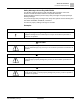
About This Document Document Revision History Documentation Conventions The following table lists conventions to help you use this document in a quick and efficient manner. Convention Examples Numbered Lists (1, 2, 3…) indicate a procedure with 1. Turn OFF power to the field panel. sequential steps. 2. Turn ON power to the field panel. 3. Open the cabinet. One-step procedures are indicated by a bullet point.
About This Document Document Revision History Safety Messages According ANSI Z535.6 The following examples show the ANSI standard safety messages used in this document to draw the reader’s attention to important information. ANSI distinguishes between personal injury safety messages and property damage warning messages. The personal injury safety messages have safety alert symbols and the following alert level labels: DANGER!, WARNING!, CAUTION! The label for property damage messages is: NOTICE.
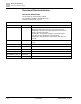
About This Document Document Revision History Document Revision History Document Identification The document ID is structured as follows: ID_Language(COUNTRY)_ModificationIndex Example: A6Vnnnnnnnn_enUS_a Document Revision History Modification Index Edition Date Brief Description A6V10415932_enUS_e 2022-02-01 Updates and corrections to: - MOSA Kit: S2E model DG1 TX; nylon spacers and nuts - Installing the PS-5A PS and S2E: nylon spacers and nuts to prevent a ground fault trouble - Installing the Config
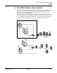
The XNET Monitor-Only Solution 1 1 The XNET Monitor-Only Solution The XNET monitor-only solution provides a view-only interface into an XNET network via any non UL ITE listed PC, which runs the management station software. This means that a user can view events from the XNET network, but will not be able to control the attached fire alarm panels.
2 The MOSA Kit 2 The MOSA Kit The MOSA kit is UL/ULC listed as an ancillary device for Siemens management station.
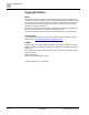
The MOSA Kit 1 2 2 3 4 5 Fig.
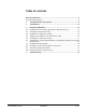
3 Installing the MOSA Kit Installing the PS-5A Power Supply and the S2E (Perle IOLAN) 3 Installing the MOSA Kit The MOSA kit installation workflow includes the following steps: 1. Install [➙ 12] the PS-5A power supply and the S2E (Perle IOLAN) inside the ENCL-01 enclosure. 2. Configure the S2E (Perle IOLAN): – – – – – – Power [➙ 14] the S2E (Perle IOLAN). Install [➙ 15] the configuration software on the management station. Assign [➙ 15] an IP address to the S2E (Perle IOLAN).
Installing the MOSA Kit 3 Installing the PS-5A Power Supply and the S2E (Perle IOLAN) 2 3 4 5 6 1 7 8 9 10 Fig.
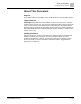
3 Installing the MOSA Kit Powering the S2E (Perle IOLAN) 2 – – 3 + 4 + 1 – 4 3 2 + 1 Fig. 4: Connecting the TB1 Terminal Block to the S2E (Perle IOLAN) Power Input Item Description 1 TB1 terminal block 2 Black wire (–) 3 Red wire (+) 4 S2E (Perle IOLAN’s) power input 3.2 Powering the S2E (Perle IOLAN) To configure the S2E (Perle IOLAN), the S2E must be powered. Any 24V DC power supply listed for fire, with limited power, regulated output can be used.
3 Installing the MOSA Kit Installing the Configuration Software 3.3 Installing the Configuration Software The following software will be installed by the management station installer (V4.2 and later) for all systems. ● The Device Manager, to configure the S2E (Perle IOLAN). ● The TruePort Management Tool, to manage the communication between the S2E (Perle IOLAN) and the management station.
3 Installing the MOSA Kit Assigning an IP Address to the S2E (Perle IOLAN) Fig. 6: The S2E (Perle IOLAN) Switch Fig. 7: Discovering the Connected S2E (Perle IOLAN) Fig.
3 Installing the MOSA Kit Configuring the S2E (Perle IOLAN) 3.5 Configuring the S2E (Perle IOLAN) The S2E (Perle IOLAN) is powered and connected to the management station. 1. Start the Device Manager. 2. In the Establish connection to... window, select the S2E (Perle IOLAN) and click OK. The Login window displays. 3. In the Login window, type the password (default: superuser). The configuration menu displays in the Device Manager main window. 4. In the left-hand tree, select Network > IP Settings.
3 Installing the MOSA Kit Configuring the S2E (Perle IOLAN) 20. Click OK. 21. In the Device Manager main window, click File > Exit. A message box displays to confirm the download of the configuration to the IOLAN. 22. Click Yes. Fig. 9: Giving the S2E (Perle IOLAN) a Name Fig.
Installing the MOSA Kit 3 Configuring the S2E (Perle IOLAN) Fig.
3 Installing the MOSA Kit Configuring the Communication Between the Management Station and the S2E (Perle IOLAN) Fig. 12: Hardware Settings for TruePort Profile 3.6 Configuring the Communication Between the Management Station and the S2E (Perle IOLAN) The communication between the management station and the S2E (Perle IOLAN) requires a TruePort adapter. To create and configure a TruePort adapter, proceed as follows: 1. Start the TruePort Management Tool. 2. Click Add. 3.
3 Installing the MOSA Kit Configuring the Communication Between the Management Station and the S2E (Perle IOLAN) 7. At the end of the installation process, click Finish. The TruePort adapter is listed in the TruePort Management Tool. 8. Select the TruePort adapter. 9. Click the Properties button. The TruePort adapter properties window displays. 10. Click the Configuration tab. 11. Click the Settings button. The TruePort adapter settings window displays. 12.
3 Installing the MOSA Kit Configuring the Communication Between the Management Station and the S2E (Perle IOLAN) Fig. 14: TruePort Adapter Properties Fig.
Installing the MOSA Kit 3 Configuring the Communication Between the Management Station and the S2E (Perle IOLAN) Fig. 16: Client-Initiated Connection Settings Fig.
3 Installing the MOSA Kit Installing the XND-M Adapter 3.7 Installing the XND-M Adapter 1. Remove the power source from the TB1 terminal block (1). 2. Remove and discard the two standoffs on the XND-M adapter's female DB-9 connector. 3. Plug the NIC-C to XND-M interface cable into the XND-M adapter's male DB-9 connector and secure the NIC-C to XND-M interface cable with the captive locking screws. 4. Uninstall and set aside the mounting bracket for the XND-M adapter and the two nuts. 5.
3 Installing the MOSA Kit Installing the XND-M Adapter 3 1 4 5 2 6 7 8 9 Fig.
3 Installing the MOSA Kit Mounting and Connecting the ENCL-01 Enclosure 3.8 Mounting and Connecting the ENCL-01 Enclosure The ENCL-01 enclosure must be mounted near the XLS/Modular CAB-1/CAB-2/CAB3 enclosure and must be connected to the XLS/Modular NIC-C monitor port and to the management station. DANGER Remove all system power before installation, first the battery and then the AC supply. The NIC-C card is configured to connect to the XNET. 1.
3 Installing the MOSA Kit Connecting a NRC-based XNET 3.9 Connecting a NRC-based XNET When a management station connects to a NRC-based XNET network of FireFinderXLS or Modular products, the MOSA XND-M connection requires additional interface hardware: the NRC/NIC bridge. In such an installation, the XND-M interface cable connects to a NIC-C module, which in turn is connected to a dedicated NRC module. Connect a management station to the closest XLS network system (rev. PMI07.
3 Installing the MOSA Kit Connecting a NRC-based XNET 1 3 2 4 1 2 9 3 10 4 11 5 12 6 13 7 14 8 15 1 2 16 9 3 10 4 11 5 12 6 13 7 14 8 15 16 5 CC-5 NRC NRC CC-2/CC-5 NIC-C 6 9 IIC P1 7 8 NRC/NIC Bridge Fig.
3 Installing the MOSA Kit Starting the Monitor-only Connection 3.10 Starting the Monitor-only Connection You created and configured an XNET network in the management station (Desigo CC or Cerberus DMS). 1. Start the Device Manager and check that the S2E (Perle IOLAN) is discovered. 2. Start the management station. The Device Manager manages the connection to the XNET network.
4 Troubleshooting 4 Troubleshooting Problem Situation Do the following... The Device Manager does not automatically discover the S2E (Perle IOLAN). The S2E (Perle IOLAN) cannot be ● discovered on some occasions. ● 30 | 31 02/01/2022 Reset the management station Ethernet port to obtain the IP address automatically. In the DeviceManager utility, click Refresh.
Issued by Siemens Industry, Inc. Smart Infrastructure 1000 Deerfield Pkwy Buffalo Grove IL 60089 +1 847-215-1000 © Siemens Industry, Inc., 2014-2022 Technical specifications and availability subject to change without notice.