
- enhanced real-time ethernet controller User Manual
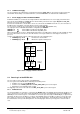

f/MHz
t/µs
t
LOCK
= 645 µs
35
Power-up PLL
a
c
t
i
v
e
R
e
s
e
t
300
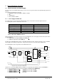
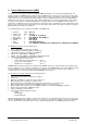
Figure 11: Power-Up Phase of the PLL
The lock status of the PLL is monitored by the hardware. Loss of the input clock and PLL not locked status is signaled
with interrupt FIQ3. The state of the PLL can also be read out in the PII_STAT_REG system control register. A filter is
integrated at the RESET_N input, which suppresses spikes up to 5 ns.
The SRST_N reset signal is available for the debugger. The signal is activated while RESET_N is active and the internal
PowerOn-reset extension is running. This enables the debugger to recognize the PowerOn-reset phase.
5.2.2 Hardware Reset
The hardware reset is trigger drain output). The reset is normally only activated
by the debugger. During the nal logic is reset without
ed via the bidirectional SRST_N pin (open
active hardware-reset phase, the entire inter
the clock system. In
addition, the configuration and boot pins are not
read in or saved, either.
ase, the debugger can communication with
om the reset address. As with the RESET_N
eset, the boot mode that was saved during
are reset, the PowerOn/Hardware-reset bit is
cted by the triggered reset function. Th
software monitoring by the hardware. Monito
watchdog is activated. Retriggering the time
gered. If the timer is not retriggered, the w
ve with the WD_RES_FREI bit. The watch
etching (PV). The watchdog reset resets the
are reset, the watchdog reset bit is set in the
the triggered reset function. This register can
, the watchdog event on GPIO[15] can be signa
During the hardware reset ph the embedded ICE logic via the JTAG interface,
enabling a single-step trace fr input a filter that suppresses spikes up to 5 ns
is also integrated here.
For booting after a hardware r the PowerOn reset is used.
During PowerON and hardw set in the RES_STAT_REG system control
register, which remains unaffe is register can be evaluated after a restart.
5.2.3 Watchdog Reset
The watchdog reset involves ring is based on a time setting in the watchdog
timer. This is started when the r at a specified reload value prevents the
watchdog reset from being trig atchdog reset is enabled after the timer expires
if the watchdog function is acti dog reset is controlled in the ERTEC 200 by
means of assignable pulse str complete ERTEC 200 circuit.
As is the case with the hardw RES_STAT_REG system control register,
which remains unaffected by be evaluated after a restart.
Via the alternative function led to an external host processor.
The watchdog reset also resets the IRT switch controller when the EN_WD_SOFT_RES_IRTE bit is set in the
RES_CTRL_REG system control bit.
For booting after a watchdog reset, the boot mode that was saved during the PowerOn reset is used.
5.2.4 Software reset
A software reset can be triggered in the ERTEC 200 by setting the XRES_SOFT bit in the reset control register. The
software reset bit is set in the RES_STAT_REG system control register when the reset is triggered. The
RES_STAT_REG system control register is unaffected by the triggered reset function and can be evaluated after restart.
The software reset also resets the IRT switch controller when the EN_WD_SOFT_RES_IRTE bit is set in the
RES_CTRL_REG system control bit.
For booting after a software reset, the boot mode that was saved during the PowerOn reset is used.
5.2.5 IRT Switch Reset
The switch module can be reset by means of a register in the IRT switch. The reset function of the switch module is
retained until the bit is revoked again. The internal PHYs can be reset either via the RESET_N pin or by the IRT switch
controller via PHY_RES_N. The selection of the reset used for the PHYs is specified with the PHY_RES_SEL bit in the
PHY_CONFIG system control register. Whenever the SMI interface is not activated in the IRT switch the PHY_RES_N is
active and, if the appropriate selection is made, maintains the PHYs in reset state (little power loss from the PHYs) for
this phase.
Copyright © Siemens AG 2007. All rights reserved. 66 ERTEC 200 Manual
Technical data subject to change Version 1.1.0