Operating Instructions · 11/2007 OPERATING INSTRUCTIONS ET 200pro FC simatic ET 200pro FC
s Product Information SIMATIC ET 200S FC SIMATIC ET 200pro FC Edition 11/2007 This product information sheet describes the behavior of the above mentioned inverters (Firmware version V3.0), that is not described in the associated documentation, edition 11/2007, Firmware version 3.0.
Foreword Safety information 1 SIMATIC Description 2 Frequency converters ET 200pro FC Interfaces 3 Installation 4 Configuration / project engineering 5 Commissioning (hardware) 6 Commissioning and optimization (software) 7 Series commissioning and operation 8 Alarm, fault, and system messages 9 Operating Instructions Firmware version V3.
Safety Guidelines This manual contains notices you have to observe in order to ensure your personal safety, as well as to prevent damage to property. The notices referring to your personal safety are highlighted in the manual by a safety alert symbol, notices referring only to property damage have no safety alert symbol. These notices shown below are graded according to the degree of danger. DANGER indicates that death or severe personal injury will result if proper precautions are not taken.
Foreword SIMATIC documentation A wide variety of manuals is available for SIMATIC hardware and software. You can access an overview of available documentation and languages, which is updated on a regular basis, by visiting us on the Internet at: http://www.automation.siemens.com/simatic/portal/html_76/techdoku.htm. The online catalog and ordering system are available at: https://mall.automation.siemens.com/de/guest/guiRegionSelector.
Foreword Validity of the manual This manual is valid for the specified components of the ET 200 decentralized I/O device. The manual describes the components based on the data valid at the time of its release. We reserve the right to issue a Product Information which contains up-to-date information about new components and new versions of components.
Foreword Position in the information landscape The following table provides an overview of the contents of the ET 200pro-System manuals Manual Contents ET 200pro distributed I/O devices • • • • Installing and connecting Commissioning and diagnostics Functions Technical data – Interface modules – Power modules – Connection modules – Electronic modules SIMATIC ET 200pro motor starters • • • • Installing and connecting Commissioning and diagnostics Device functions Technical data – Backplane bus module
Foreword A&D Technical support 24-hour technical support is provided by four main centers worldwide. A&D Global service and support Online Service and support In the first instance for customer-support, contact should always be made with the regional (country based) sales/marketing/service organisations. http://support.automation.siemens.com For technical-support, the most optimised way to do this is via the Internet based SupportRequest. http://www.siemens.
Foreword Contact address Should any questions or problems arise while reading this manual, please contact Siemens at the following address: Siemens AG Automation & Drives A&D SD SPA PM4 Postfach 3269 D-91050 Erlangen Germany e-Mail: documentation.sd@siemens.com Regional contacts For questions regarding services, prices and conditions of technical support, please contact your local Siemens partner.
Table of contents Foreword ................................................................................................................................................... 5 1 Safety information.................................................................................................................................... 17 2 Description............................................................................................................................................... 21 3 4 5 2.
Table of contents 6 7 8 9 12 Commissioning (hardware) ...................................................................................................................... 77 6.1 Startup of ET 200pro................................................................................................................... 78 6.2 Creating a drive configuration with STARTER............................................................................ 79 Commissioning and optimization (software) ..............
Table of contents 9.6 10 11 12 Technical data ....................................................................................................................................... 147 10.1 Technical data............................................................................................................................147 10.2 General ambient conditions .......................................................................................................149 Dimensional drawings............
Table of contents Table 4-8 Power jumper connector ............................................................................................................. 53 Table 5-1 Operation with standard telegram 1............................................................................................ 59 Table 5-2 Standard telegram 1.................................................................................................................... 59 Table 6-1 Preconditions for commissioning .........
Table of contents Table 12-16 Changeable parameter attributes ..............................................................................................183 Table 12-17 Data type of parameter attributes ..............................................................................................183 Table 12-18 Data type of parameter attributes ..............................................................................................184 Table 12-19 Quick commissioning parameter attributes....
Table of contents Figure 5-11 Inserting an IO Controller ............................................................................................................ 66 Figure 5-12 Creating a network ...................................................................................................................... 66 Figure 5-13 Selecting the ET 200pro from the hardware catalog .................................................................. 67 Figure 5-14 Specifying device names ..............
Safety information 1 Safety instructions The warnings, safety information and remarks that follow are intended to be used as both safety measures for users and as measures that can be put in place to avoid damage to the product or to components of the connected machines.
Safety information The power-supply, direct-current and motor terminals as well as the brake cables and thermistor cables can carry hazardous voltages even when the converter is out of service. After interruption of the power supply, wait at least 5 minutes until the device has discharged itself. Only then carry out installation work. It is strictly forbidden to isolate the device from the supply on the motor side; isolation from the supply must always be carried out on the supply side of the converter.
Safety information NOTICE This manual is to be kept somewhere close to the devices and must be easily accessible for all users. If measurements or tests have to be carried out on the live device, the stipulations of safety regulation BGV A2 are to be complied with, especially § 8 "Permissible deviations during work on live parts". Suitable electronic tools are to be used.
Description 2.1 2 The frequency converter Description The ET 200Pro FC is a compact frequency converter that is completely embedded in the distributed I/O system of the ET 200pro. The individual components can be configured in STEP 7 HW Config or integrated into other configuration systems using a GSD (device master file).
Description 2.1 The frequency converter ● Fast current limitation (FCL) for trip-free operation ● Energy recovery into line supply system ● No braking resistor required ● Robust EMC design ● Can be configured for a wide range of applications ● Powerfail-proof storage of parameter settings on either EEPROM or MMC ● Control and diagnostics using a higher-level controller (e.g.
Description 2.
Description 2.2 Components for assembling a frequency converter 2.2 Components for assembling a frequency converter General information The following section provides an overview of configuration options for the frequency converters in the ET 200pro distributed I/O system. Other general information on the ET 200pro distributed I/O system can be found in the manual entitled "ET 200pro Distributed I/O System".
Description 2.2 Components for assembling a frequency converter Illustration 2 Components Function Interface module for PROFINET DP, with bus module The interface module interconnects the ET 200pro with the DP master and prepares the data for the electronic modules. The unit is delivered with the terminating module, and the interface module is already mounted on the bus module. • The bus module is the mechanical and electrical connection element between the various ET 200pro modules.
Description 2.2 Components for assembling a frequency converter Table 2-2 Illustration Components of the fail-safe frequency converter with F-RSM Components Function 1 Rack, wide The ET 200pro bus modules, onto which the electronic modules are screwed, must be mounted on the rack. 2 Interface module for PROFINET DP, with bus module Lengths: 0.5 m, 1 m The interface module interconnects the ET 200pro with the DP master and prepares the data for the electronic modules.
Description 2.
Description 2.2 Components for assembling a frequency converter Table 2-3 Illustration Components of the fail-safe frequency converter with F-Switch Components Function 1 Rack, wide The ET 200pro bus modules, onto which the electronic modules are screwed, must be mounted on the rack. 2 Interface module for PROFINET DP, with bus module Lengths: 0.5 m, 1 m The interface module interconnects the ET 200pro with the DP master and prepares the data for the electronic modules.
Description 2.3 Limit / maximum expansion of the ET 200pro modules that can be connected 2.3 Limit / maximum expansion of the ET 200pro modules that can be connected Maximum expansion for each IM 154 interface module When configuring the system, please note the following: ● One ET 200pro station can be configured with up to 16 modules for each IM154 interface module.
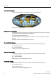
Description 2.4 Overview of the LEDs 2.4 Overview of the LEDs Status display through LEDs The SIMATIC ET 200pro FC frequency converters have a number of functions and statuses that can be displayed by means of LEDs.
Description 2.4 Overview of the LEDs Description of the LEDs LEDs Description System failure (SF) The "System failure" LED indicates a general system error in either the software or hardware. Ready (RY) The Ready LED indicates whether the converter is ready; a control word is sent for this purpose. It does not show whether the drive is running or not. Final state (FS) The "Final state" LED shows whether the final state of a safety function that has been triggered has been reached.
3 Interfaces 3.1 Communication interfaces Overview The frequency converter has 3 communication interfaces. These are: ● An optical interface for commissioning the frequency converter using a PC and the RS232 interface ● A fieldbus connection Through the ET 200pro backplane bus for communicating with a higher-level control ● An MMC slot Slot for a special micro memory card (MMC). The MMC can be used as a parameter memory or for updating firmware.
Interfaces 3.1 Communication interfaces 3.1.1 Optical interface Description The ET 200pro FC frequency converter has a serial optical communication interface with USS protocol for commissioning using the STARTER commissioning software on a PC. RS232/optical conversion is performed in the cable between the PC and the frequency converter. The following components are required: ● PC with Windows 2000/Windows 2003 Server/Windows XP ● STARTER commissioning software (version 4.
Interfaces 3.2 PTC/KTY84 interface 3.1.3 MMC interface (Micro Memory Card) Description The MMC interface can be used to back up frequency converter parameters on an external MMC and, if required, download them back onto the frequency converter. Possible fields of application for the MMC The MMC can be used as a parameter memory: ● Uploading a parameter set onto an MMC ● Transferring parameters from an MMC when exchanging the frequency converter ● Automatic download of a parameter set from an MMC.
Interfaces 3.3 Interface to the motor holding brake 3.3 Interface to the motor holding brake Description A motor holding brake can be controlled using the ET 200pro FC. The electrical connection between the frequency converter and the brake is established by plugging the motor cable into the frequency converter. Use of the motor holding brake is optional.
4 Installation 4.1 Prerequisites and maximum expansion Maximum mechanical expansion The maximum expansion of an ET 200pro is reached when one of the rules outlined below applies: Table 4-1 Maximum mechanical expansion Features Rule Number of modules max. 16 electronic modules Width of ET 200pro max.
Installation 4.2 Mounting the racks 4.2 Mounting the racks The frequency converter is mounted on the wide rack. The following versions are possible: ● Rack, wide ● Rack, compact-wide Dimensions 500 476 182 110 119 182 27 220 231 27 35 56 9 12 35 182 27 110 119 182 220 231 27 13 1000 976 56 9 12 35 27 110 119 max.
Installation 4.2 Mounting the racks PD[ Figure 4-2 Dimensional drawing of wide module rack Tools required ● Wrench or screwdriver, matching the selected fixing screws. ● Stripping tool and crimp tool for the grounding cable.
Installation 4.2 Mounting the racks Accessories required Table 4-3 Rack and grounding cable For... you can use ... Explanation Outer fixing screws M8 cylindrical head screw according to ISO 1207/ISO 1580 (DIN 84/DIN 85) Choose a suitable screw length for your configuration. You also need 8.4 mm washers according to ISO 7092 (DIN 433) Hexagonal head screw, M8, according to ISO 4017 (DIN 4017) Grounding cable Insulated cable, conductor cross-section: min.
Installation 4.3 Mounting the interface module 4.3 Mounting the interface module The interface module connects ET 200pro to PROFIBUS DP/ PROFINET IO and supplies power to the electronic modules. Requirements ● Interface module for PROFIBUS DP – The terminating module is removed from the interface module. – The rack has been mounted. ● Interface module for PROFINET IO – The terminating module is removed from the interface module. – The SIMATIC Micro Memory Card is inserted. – The rack has been mounted.
Installation 4.
Installation 4.4 Mounting the bus module 4.4 Mounting the bus module The bus module connects the frequency converter to the ET 200pro backplane bus. Requirements ● The interface module is mounted on the rack. ● Additional bus modules can be mounted next to the interface module Procedure 1. Snap-mount the bus module onto the rack. 2. Push the bus module to the left until it engages into the interface module or the previous electronic module.
Installation 4.5 Mounting the terminating module 4.5 Mounting the terminating module The ET 200pro station must be terminated with the terminating module. Requirements ● All bus modules are mounted on the rack. Required tools Cross-tip screwdriver, size 2 Procedure 1. Mount the terminating module onto the rack. 2. Slide the terminating module to the left up against the last bus module. Note Do not screw the terminating module to the rack (2 recessed head screws at the front, torque 1.
Installation 4.
Installation 4.6 Mounting the connection module for IM154 4.6 Mounting the connection module for IM154 There are various connection modules with different connection methods for IM 154 ● CM IM DP ECOFAST Cu ● CM IP DP M12, 7/8" ● CM IM DP Direct. Requirements The interface module must be mounted. Required tools Cross-tip screwdriver, size 2 Procedure 1.
Installation 4.
Installation 4.7 Mounting the frequency converters 4.7 Mounting the frequency converters The frequency converter is unpacked and screwed onto the bus module using 8 screws. Note When removing the device from the packaging, be sure not to touch or damage the rear plug. Remove the device and place it on a even surface.
Installation 4.7 Mounting the frequency converters Requirements The bus module for the frequency converter and all the modules to the left are mounted. Tools required Cross-head screwdriver, size 2. Procedure 1. Plug the frequency converter into the bus module so that the two domes on the rear engage in the guide holes of the bus module. 2. Holding the frequency converter firmly against the module rack, screw it in place with 4 screws on the top and 4 screws on the bottom.
Installation 4.8 Wiring in the ET 200pro system 4.8 Wiring in the ET 200pro system Communication and auxiliary voltages are routed with standard connectors through the interface module (or power modules) and the backplane bus to the frequency converter and do not have to be considered here. The power unit of the frequency converter is rated for direct operation on TN and TT line supply systems with a grounded PEN conductor with a rated voltage of 3 AC 400 V.
Installation 4.8 Wiring in the ET 200pro system Tools required If you use prefabricated standard cables, no tools will be needed for the frequency converter side. You can adapt the motor side to your needs. If you want to prepare the cables yourself, the following tools, among others, will be needed. Table 4-4 Tools Harting order no. Crimping tool (Q8/0 and Q4/2) Inserts for crimping tool -- 0999 000 0001 0.5 mm2 (AWG 20) 0999 000 0007 1.
Installation 4.
Installation 4.8 Wiring in the ET 200pro system Motor cable Motor cable up to 10 m are available under the following order designation: ● 6ES7194-1LA01-0AA0 (1.5 m) ● 6ES7194-1LB01-0AA0 (3.0 m) ● 6ES7194-1LC01-0AA0 (5.0 m) ● 6ES7194-1LD01-0AA0 (10.0 m). Larger lengths up to 15 m can be obtained from our service providers. NOTICE A metallic connector enclosure must be used for connecting. The shield of the motor cable must be connected to a large area of the motor housing (for EMC reasons).
Installation 4.9 Mounting a fail-safe frequency converter 4.
Installation 4.9 Mounting a fail-safe frequency converter 4.9.1 Mounting the bus module for F-RSM and mounting the repair switch module The Safety Local function of the F-RSM, its use, control elements and connections are described in detail in the manual SIMATIC ET 200pro Motor Starters. Therefore, only the most important points concerning its use with a frequency converter will be covered here. The 3RK 19222-BA01 bus module is required to accommodate a Safety Local repair switch module.
Installation 4.9 Mounting a fail-safe frequency converter 4.9.2 Mounting the module for the F-Switch The function, use, control elements and connections of the F-Switch are described in detail in the manual ET 200pro Distributed I/O Devices - Fail-safe Modules Therefore, only the most important points concerning its use with a frequency converter will be covered here. The 6ES7 xxxxxxx bus module is required to accommodate an F-Switch. It is mounted to the left of the frequency converter bus module.
Configuration / project engineering 5.1 5 Integrating ET 200 frequency converters into automation systems with STEP 7 General information on STEP 7 STEP 7 is the basic package for configuring and programming SIMATIC automation systems. It is part of the SIMATIC industry software. The STEP 7 basic package is available in several versions. "STEP 7 for applications running on SIMATIC S7 300/400" is required for integrating ET 200pro frequency converters.
Configuration / project engineering 5.2 Installation of the hardware information in SIMATIC Manager 5.2 Installation of the hardware information in SIMATIC Manager 5.2.1 Installation of a hardware support package (HSP) The HSP (hardware support package) file defines the system environment of an ET 200pro station. To be able to configure an ET 200pro with the HW Config tool, the relevant HSP file must be installed first.
Configuration / project engineering 5.3 Configuring the communication 5.3 Configuring the communication The frequency converter is operated by means of PROFIdrive profile.
Configuration / project engineering 5.3 Configuring the communication catalog, a PROFIBUS DP system is provided in the hardware configuration. After setting the parameters for the master, the slave – in this particular case the ET 200pro station – must be selected from the hardware catalog and placed on the PROFIBUS line. This is done by inserting an IM 154. The PROFIBUS address of the ET 200pro station must also be specified in IM 154.
Configuration / project engineering 5.
Configuration / project engineering 5.3 Configuring the communication Inserting a converter in an ET 200pro slot From the hardware catalog select "FC 1.1/1.5 kW; standard telegram 1" and pull it onto the slot. Figure 5-5 Selecting the frequency converter Figure 5-6 Frequency converter in slot With this selection the user specifies which frequency converter will be used (standard or fail-safe).
Configuration / project engineering 5.3 Configuring the communication Figure 5-7 Setting the address in the I/O map Note The input and output address area of the frequency converter must be the same. Parameter The application ID provides a unique means of identification and is assigned by the user. Note If the same application ID is entered for several frequency converters, they can be used interchangeably. Frequency converters with the same application ID must be parameterized in the same way.
Configuration / project engineering 5.3 Configuring the communication Figure 5-8 Parameter Points to note when using the PROFIdrive profile The alarm mode of the ET 200pro slave must be set to DPV1. ● Double-click the ET 200pro system ● Select the "Operating parameters" tab Figure 5-9 Operating parameters ● The diagnostic interrupt parameter of the frequency converter enables the S7 system diagnostics in PROFIdrive mode. – No diagnostic messages: 0 – Diagnostic messages: 1.
Configuration / project engineering 5.3 Configuring the communication Figure 5-10 5.3.2 Setting the device-specific parameters Generating a hardware configuration for PROFINET in the SIMATIC Manager Description The following example of an ET 200pro FC frequency converter with an "IM 154-4 PN HF" interface module will be used to demonstrate how to generate a PROFINET configuration with HW Config in the SIMATIC Manager.
Configuration / project engineering 5.3 Configuring the communication Inserting the IO controller using the context menu of the CPU PROFINET IO interface Figure 5-11 Inserting an IO Controller After the PROFINET IO system was inserted, a network must be created for it. In the context menu of the PN-IO click on "Object properties". In the window which then opens, click the "General" tab and then the "Properties" button to create a new network.
Configuration / project engineering 5.3 Configuring the communication Inserting the ET 200pro system in the IO Controller Figure 5-13 Selecting the ET 200pro from the hardware catalog Specifying the device name In the PROFINET version, the address of the I/O devices is assigned via their device names. To do this, click the ET 200pro station in the HW Config tool to open its properties. You can then enter any unique device name you like.
Configuration / project engineering 5.3 Configuring the communication The ET 200pro must then declare the name that has been selected. This can be performed in 2 different ways: ● Direct route --> The NameOfStation is written via PROFINET to the MMC of the IM in the ET 200pro: The prerequisite for this is a PC with PG functionality, which can establish an Ethernet connection with the ET 200pro. An MMC must also be inserted in the IM. The name is assigned in the SIMATIC Manager.
Configuration / project engineering 5.3 Configuring the communication From the hardware catalog select "FC 1.1/1.5 kW; standard telegram 1" and pull it onto the slot. Figure 5-16 Selecting the frequency converter Figure 5-17 Frequency converter in slot Settings for the frequency converter Double-clicking the frequency converter opens the property view with the following tabs: ● General ● Adresse ● Parameter.
Configuration / project engineering 5.3 Configuring the communication Address/ID Setting an address in the I/O map The start address configured here is accepted in the user program as the "LADDR" input parameter for the blocks in the user program. Figure 5-18 Setting the address in the I/O map Note The input and output address area of the frequency converter must be the same. Parameter The application ID provides a unique means of identification and is assigned by the user.
Configuration / project engineering 5.3 Configuring the communication Figure 5-19 Parameter Points to note when using the PROFIdrive profile The alarm mode of the ET 200pro slave must be set to DPV1. ● Double-click the ET 200pro system ● Select the "Operating parameters" tab Figure 5-20 Operating parameters ● The diagnostic interrupt parameter of the frequency converter enables the S7 system diagnostics in PROFIdrive mode. – No diagnostic messages: 0 – Diagnostic messages: 1.
Configuration / project engineering 5.3 Configuring the communication Figure 5-21 5.3.3 Setting the device-specific parameters Creating a fail-safe configuration in SIMATIC Manager Description A configuration is carried out using the fail-safe I/O module F-Switch or F-RSM on PROFIBUS DP. The procedure with PROFINET IO is similar and will not be described separately.
Configuration / project engineering 5.3 Configuring the communication Selection of F-Switch Selection of F-RSM The length of the process image of F-RSM is always one byte; only the start address must be set in the PI.
Configuration / project engineering 5.3 Configuring the communication Group diagnostics can be activated or deactivated. Figure 5-23 Specifying the diagnostics properties You can use drag-and-drop to position the fail-safe frequency converter to the right of the FSwitch or F-RSM module. The configuration sequence is identical to the one used when generating a PROFIBUS configuration in the SIMATIC Manager.
Configuration / project engineering 5.3 Configuring the communication Parameter description The variable parameters of the fail-safe modules can be found in the manual entitled ET 200pro Distributed I/O Devices - Fail-Safe Modules. PROFIsafe address and address assignment The PS address is set using a 10-pin DIP switch on the left-hand side of the module housing. When carrying out parameterization using the PG, the user must specify the PS address selected for the module in binary code format.
6 Commissioning (hardware) Introduction Hardware commissioning involves the ET 200pro station and the drive components. The following procedure describes by way of example the commissioning of a minimum configuration on PROFIBUS DP, with an S7 controller as the master and STARTER software directly on the optical interface of the frequency converter. It is assumed that the user has the necessary knowledge of STARTER to create a drive configuration and to use the operating panel.
Commissioning (hardware) 6.1 Startup of ET 200pro 6.1 Startup of ET 200pro Procedure Switch on the power supply for the ET 200pro station (electronics/encoder supply 1L+ for the ET 200pro). Mode of operation The illustration below represents the startup routine of the ET 200pro with a frequency converter.
Commissioning (hardware) 6.2 Creating a drive configuration with STARTER Note The SF LED on the S7 will not necessarily light up if an error occurs on the ET 200pro FC. The S7 receives notification of an error only if diagnostic messages are enabled in the converter. This is done via parameterization in HW Config. If diagnostic messages are disabled, errors in the converter can only be read by means of the red LED on the converter. 6.
Commissioning (hardware) 6.2 Creating a drive configuration with STARTER Checking the motor terminal box (IEC/NEMA motor) For commissioning to be successful, it is important that the interconnection in the motor terminal box (see image below) corresponds to the entry for the rated motor voltage (P0304)/rated motor current (P0305). IEC motor : 8 9 8 9 : 8 : 8 9 8 9 : 8 9 : 9 : Delta connection Star circuit configuration E.g.
Commissioning (hardware) 6.2 Creating a drive configuration with STARTER Entering the type plate data The following should be noted when entering the type plate data/ESB data: ● The phase-to-phase voltage (voltage U12 between external lines L1 and L2) and/or phase-to-phase current I1 is always specified on the type plate. ● The rated motor voltage (P0304)/rated motor current (P0305) must always be entered according to the motor circuitry (delta/star).
Commissioning and optimization (software) 7.1 7 Commissioning sequence The sequence in which the software of a frequency converter in an ET 200 station is commissioned depends on how complex the drive application is, and on the automation structure. The basic drive functions and the higher-level controller are commissioned first and are then specialized, optimized and the drive application generated.
Commissioning and optimization (software) 7.1 Commissioning sequence Table 7-1 First commissioning and optimization Steps Description Tool 1 Commissioning and optimizing the frequency converter/motor combination Basic parameterization has already been carried out when commissioning the hardware (quick commissioning). STARTER at the RS232 interface The motor type plate data and the frequency converter factory settings form the basis for this.
Commissioning and optimization (software) 7.2 Commissioning and optimization of the frequency converter and motor combination 7.2 Commissioning and optimization of the frequency converter and motor combination Description If there is still no matching parameter set for the drive, then quick commissioning including a motor data identification routine must be carried out - both for the closed-loop vector control and the V/f control.
Commissioning and optimization (software) 7.2 Commissioning and optimization of the frequency converter and motor combination STARTER projects STARTER can be used to either create a new project or open an existing one. To create a new project in STARTER, any of the following procedures can be used: ● Find frequency converter ● Wizard ● Select frequency converter When an existing project is opened or a new one created, STARTER will be in offline mode. ("Connect to target system") button.
Commissioning and optimization (software) 7.
Commissioning and optimization (software) 7.
Commissioning and optimization (software) 7.2 Commissioning and optimization of the frequency converter and motor combination The motor data identification routine operates with the results of the "Complete parameterization" P0340 = 1 or the motor equivalent diagram data which was last saved. The results become increasingly better the more times that the identification routine is executed (up to 3 times).
Commissioning and optimization (software) 7.2 Commissioning and optimization of the frequency converter and motor combination Parameter settings WARNING The motor data identification routine MUST not be used for loads which are potentially hazardous (for example, suspended loads for crane applications).
Commissioning and optimization (software) 7.3 Commissioning and optimization of the drive application 7.3 Commissioning and optimization of the drive application After the motor and converter combination is commissioned by quick commissioning, parameters must be adapted and set to suit the requirements of the specific application. Note According to the factory setting, parameter changes are saved in the volatile memory (RAM) of the converter.
Commissioning and optimization (software) 7.3 Commissioning and optimization of the drive application Temperature encoder Parameters Description (parameters and factory settings in bold) Setting P0601 = 0 or P0601 = … Motor temperature encoder 0: No encoder (→ P0610) 1: PTC thermistor (→ P0604) 2: KTY84 (→ P0604) P0604 = 130° Motor temperature limit Enter the alarm limit value of the motor overtemperature protection.
Commissioning and optimization (software) 7.3 Commissioning and optimization of the drive application JOG frequency Parameter Description P1057 = 1 JOG Enable P1057 = 0 JOG-function disabled P1057 = 1 JOG-function enabled (default) P1058 = 5 JOG frequency right Frequency in Hz when the motor is being jogged in the clockwise direction. P1059 = 5 JOG frequency left Frequency in Hz when the motor is being jogged in the counter-clockwise direction.
Commissioning and optimization (software) 7.3 Commissioning and optimization of the drive application Skip Frequency Parameter Description P1091 = 7.5 Skip frequency 1 (entered in Hz) Avoids mechanical resonance effects and suppresses (skips) frequencies in the range around the skip frequency ± P1101 (skip frequency bandwidth). P1092 = 0.0 Skip frequency 2 P1093 = 0.0 Skip frequency 3 P1094 = 0.0 Skip frequency 4 P1101 = 1.
Commissioning and optimization (software) 7.3 Commissioning and optimization of the drive application Parameters which must be set before ending the application settings The following parameters must be configured for every application. Parameters Description (parameter name and factory setting (if non-variable) in bold print) P1800 = 4 Pulse frequency (kHz) The pulse frequency can be changed in steps of 2 kHz. The range extends from 2 kHz to 16 kHz.
Commissioning and optimization (software) 7.4 Commissioning of communication between the S7 CPU and the frequency converter 7.4 Commissioning of communication between the S7 CPU and the frequency converter 7.4.1 Parameter settings for communication The frequency converter is operated by means of PROFIdrive profile.
Commissioning and optimization (software) 7.4 Commissioning of communication between the S7 CPU and the frequency converter ● The table below shows the parameters used to transfer process data in PROFIdrive mode. Table 7-7 Parameters for flexibly interconnecting process data in the PROFIdrive profile Telegram PZD1 STW/ZSW PZD2 HSW/HIW Connection values for setpoints, master to converter r2050.00 r2050.01 Connection parameters for actual values, converter to master P2051.00 P2051.
Commissioning and optimization (software) 7.4 Commissioning of communication between the S7 CPU and the frequency converter P0927 parameter change source Bit Description Value 0 Fieldbus 0: No 1: Yes 2 Local interface 0: No 1: Yes The factory setting for all bits is 1, i.e., the parameters can be changed from all sources. 7.4.2 Process data transfer in the PROFIdrive profile 7.4.2.
Commissioning and optimization (software) 7.4 Commissioning of communication between the S7 CPU and the frequency converter Bit Value Meaning Remarks 6 1 Enable setpoint The value selected on the ramp function generator input is enabled. 0 Inhibit setpoint The value selected on the ramp function generator input is set to 0 (zero). 1 Acknowledge error Error acknowledged with a positive pulse edge; frequency converter then switches to the "Begin interlocking" state.
Commissioning and optimization (software) 7.4 Commissioning of communication between the S7 CPU and the frequency converter Status word 1 (ZSW1) (Bits 0 to 10 according to PROFIdrive profile; bits 11 to 15 specifically for SINAMICS frequency converters). Table 7-9 Bit Value Meaning Remarks 0 1 Ready to start Power supply switched on; electronics initialized; pulses disabled.
Commissioning and optimization (software) 7.4 Commissioning of communication between the S7 CPU and the frequency converter Bit 11 12 13 14 15 7.4.2.2 Value Meaning Remarks 0 Maximum frequency not reached -- 1 -- -- 0 Warning: Motor current/torque limit reached -- 1 Motor holding brake enabled Signal can be used to control a holding brake. 0 -- -- 1 -- Motor data display overload status.
Commissioning and optimization (software) 7.4 Commissioning of communication between the S7 CPU and the frequency converter Figure 7-3 Writing PROFIdrive process data Reading PROFIdrive process data In this example, status word 1 and the instantaneous frequency are read in PROFIdrive mode. The process data are read in the cyclical time slice of the S7 (e.g. OB1) from logical address 256 of the frequency converter.
Commissioning and optimization (software) 7.4 Commissioning of communication between the S7 CPU and the frequency converter Note Please note that the way cyclic data are interpreted depends on how the frequency converter is parameterized (P2051, P0922). 7.4.3 Parameter transfer in the PROFIdrive profile 7.4.3.1 Block call Acyclic data transfer can take place parallel to cyclic data transfer.
Commissioning and optimization (software) 7.4 Commissioning of communication between the S7 CPU and the frequency converter Structure of parameter request and parameter response Each parameter request consists of three parts: Request header: ID for the request and number of parameters being accessed. Parameter address: Addressing a parameter. If multiple parameters are being accessed there will be a corresponding number of parameter addresses.
Commissioning and optimization (software) 7.4 Commissioning of communication between the S7 CPU and the frequency converter Table 7-11 Parameter response Word Response header 1. parameter value(s) (only after a "request") Byte Byte Request reference mirrored Request ID Drive object ID mirrored Qty Parameters Format Qty Values Values or error values … … n.
Commissioning and optimization (software) 7.4 Commissioning of communication between the S7 CPU and the frequency converter Field Data type Values Remark Subindex Unsigned 16 0x0001 … 0xFFFF No. 0 … 65535 Addresses the first field element of the parameter to be accessed.
Commissioning and optimization (software) 7.4 Commissioning of communication between the S7 CPU and the frequency converter Table 7-13 Description of the fields for parameter requests Field Data type Values Remark Request ID Unsigned 8 0x01 Read request (+) 0x02 Write request (+) 0x81 Read request (–) 0x82 Write request (–) Request positive, status ok Request negative, error state Mirrors the request ID and indicates whether the execution of the request has been positive or negative.
Commissioning and optimization (software) 7.4 Commissioning of communication between the S7 CPU and the frequency converter Error values in parameter responses Table 7-14 108 Error values in parameter responses Error value Meaning Remark Additional inf. 0x00 Invalid parameter number Access to a non-existent parameter. – 0x01 Parameter value cannot be modified. Attempt to modify a read-only parameter. Subindex 0x02 Low or high limit exceeded Attempted modification with value outside limits.
Commissioning and optimization (software) 7.4 Commissioning of communication between the S7 CPU and the frequency converter 7.4.3.2 Examples Writing PROFIdrive parameters In order to make use of DS47, a data block first needs to be created in Simatic Manager. This implements the data set structure using the parameter request table as a template. In this example, a data set is stored in DB47 for the purpose of changing P1082 (maximum frequency). P1082 is to be changed to 100 Hz.
Commissioning and optimization (software) 7.4 Commissioning of communication between the S7 CPU and the frequency converter Figure 7-6 DB1 (DS47 response) Once the data blocks have been created, a parameter request is written via data set DS47 using S7 function SFC58. Then, a reply data set is read with SFC59 and stored in DB1. In this example, the start of this process is triggered by a positive edge at input In0.0.
Commissioning and optimization (software) 7.4 Commissioning of communication between the S7 CPU and the frequency converter Figure 7-7 Request processing in OB1 Once the parameter request has been executed successfully, the request header (defined in DB47) must be mirrored in DB1 (requestID does not indicate any errors). To view the data currently stored in DB1, open DB1 in Simatic Manager and click the glasses icon.
Commissioning and optimization (software) 7.4 Commissioning of communication between the S7 CPU and the frequency converter Reading PROFIdrive parameters (example) In order to make use of DS47, a data block first needs to be created in SIMATIC Manager. The structure of the data set will then be implemented in it. In this example, a data set is stored in DB48 for the purpose of reading P0947 (error buffer).
Commissioning and optimization (software) 7.
Commissioning and optimization (software) 7.4 Commissioning of communication between the S7 CPU and the frequency converter Figure 7-10 114 Example DB1 after P947 has been read out successfully with F70 pending (P947.
Commissioning and optimization (software) 7.5 Commissioning of the fail-safe functions 7.5 Commissioning of the fail-safe functions General steps Those parameters that are marked with an asterisk ("*") offer a wider variety of setting options than the ones listed here. For information on additional setting options, please refer to the List Manual.
Commissioning and optimization (software) 7.5 Commissioning of the fail-safe functions Table 7-15 Parameters for fail-safe functions Parameter Description Unit Standard value Min. Max. Processor 1 (drive processor) P9601 SI enable parameter - 2 0 2 P9603 SI selection of safety source - 0 0 48 P9659 SI maximum time until test stop h 8.0 0.1 8760.
Commissioning and optimization (software) 7.5 Commissioning of the fail-safe functions When a password is entered (5 digits without leading zeros), it is compared to the password stored in r9760. If it is correct, i.e., if the two passwords match, access is granted. If the password is incorrect, the parameters for fail-safe functions are disabled and the user has to exit the commissioning mode for fail-safe functions manually using parameter P3900 = 11.
Commissioning and optimization (software) 7.5 Commissioning of the fail-safe functions Note It is essential for personnel to adhere precisely to the information/instructions and descriptive information regarding commissioning provided in the section of this manual entitled "Commissioning fail-safe functions". Whenever changes are made to safety function parameters, a new acceptance test must be carried out and the results included in the form of an acceptance report.
Commissioning and optimization (software) 7.6 Performing a reset to factory settings 7.6 Performing a reset to factory settings Overview All converter parameters can be restored to a defined original state by performing a reset to factory settings. The original state can be restored by resetting the parameters to factory default by means of P0970. These factory-set values are indicated in the parameter list by means of the abbreviation "Def".
Commissioning and optimization (software) 7.6 Performing a reset to factory settings 7.6.
Commissioning and optimization (software) 7.6 Performing a reset to factory settings 7.6.2 Resetting fail-safe parameters to default values Description Safe resetting to factory settings causes all fail-safe parameters to revert to their default values.
Series commissioning and operation 8 Overview The operating and startup characteristics depend on the settings of the converter during commissioning. The following special operating characteristics are covered in this section: ● Transfer of frequency converter parameters to external storage media ● Simple standard commissioning of several frequency converters and the response when a frequency converter is replaced ● the normal operating behavior of the frequency converter.
Series commissioning and operation 8.1 Transfer of the frequency converter parameter assignment 8.1 Transfer of the frequency converter parameter assignment The mechanisms by means of which parameters are transferred to external storage media play an important role both under normal frequency converter operating conditions and during standard commissioning and device replacement. For this reason, the different media and their associated transfer methods are explained below. 8.1.
Series commissioning and operation 8.1 Transfer of the frequency converter parameter assignment 8.1.2 Parameter transfer - Terms Upload "Upload" refers to the transfer of parameters from the internal memory to an external storage medium (e.g., MMC). Download "Download" refers to the transfer of parameters from an external storage medium to the frequency converter's internal memory.
Series commissioning and operation 8.1 Transfer of the frequency converter parameter assignment 8.1.3 Parameter transfer with MMC Upload from frequency converter to an MMC The frequency converter features an MMC slot, into which a memory card can be inserted. An upload of parameters from EEPROM to the MMC can only be triggered manually. Prerequisites: ● The upload frequency converter's power supply must be connected. ● The upload frequency converter must be in the "Ready" state.
Series commissioning and operation 8.1 Transfer of the frequency converter parameter assignment Note When making use of this download procedure, you must bear in mind the following important constraints: • During the download procedure, the frequency converter will not be able to respond to any commands. • Once the download procedure is under way, there is no way of stopping it again.
Series commissioning and operation 8.1 Transfer of the frequency converter parameter assignment Automatic download In the case of an automatic download, all parameters are transferred to the frequency converter, including the fail-safe parameters. P8458 is the parameter responsible for controlling automatic downloads on power-up. Note MMC for "automatic download" The file clone00.bin is always used for an automatic download. The user must ensure that clone00.bin (saved as "clone00.
Series commissioning and operation 8.1 Transfer of the frequency converter parameter assignment 8.1.4 Parameter transfer with PC (STARTER) Upload from frequency converter to the PC Parameters are uploaded from the frequency converter's RAM to a project file on a PC's hard disk using STARTER. STARTER can be connected via a fieldbus or directly to the frequency converter's RS232 interface. Prerequisites ● You must have a converter with a suitable parameter set at your disposal (upload converter).
Series commissioning and operation 8.1 Transfer of the frequency converter parameter assignment Prerequisites ● The download converter's power supply must be connected. ● The download converter is in the "Ready to run" state. Connect the STARTER PC to the download frequency converter via RS232 (point-to-point connection, appropriate connecting cable required) or via fieldbus, press the online button and perform the download using the ("Download project to target system") button.
Series commissioning and operation 8.1 Transfer of the frequency converter parameter assignment 8.1.6 Fault codes during upload and download Fault codes If a fault occurs during an automatic download procedure, the frequency converter returns to the parameter set that was previously stored in the EEPROM and the following fault codes are generated: Error Cause Remedy/Test F00061 No MMC inserted • • MMC faulty? Insert an MMC and attempt the upload/download again.
Series commissioning and operation 8.1 Transfer of the frequency converter parameter assignment WARNING In acknowledging fault F00395, the user assumes full responsibility for the parameters saved in the frequency converter. In the "Ready to run" state, the frequency converter can be started after acknowledgement by means of an OFF1/ON command. F00395 for fail-safe frequency converter In the case of frequency converters with integrated fail-safe functions, it is necessary to perform an acceptance test.
Series commissioning and operation 8.2 Series commissioning and replacement of the frequency converter 8.2 Series commissioning and replacement of the frequency converter 8.2.1 Application ID The application ID is an important parameter for frequency converter standard commissioning and replacement. It is specified in HW Config when the frequency converter is configured (see Planning/Configuring) and saved in the PLC.
Series commissioning and operation 8.2 Series commissioning and replacement of the frequency converter 8.2.2 Series commissioning Overview The term series commissioning refers to the process of transferring the parameter set from one frequency converter to a number of other frequency converters in order to carry out quick commissioning of identical applications (e.g. series machines or groups of converters).
Series commissioning and operation 8.2 Series commissioning and replacement of the frequency converter WARNING All the data interfaces, including the digital and analog interfaces, are reinitialized for the series commissioning. This will interfere temporarily with data transfer or will cause the digital outputs to switch over. Before embarking on series commissioning, you must secure any dangerous loads.
Series commissioning and operation 8.2 Series commissioning and replacement of the frequency converter See also Parameter transfer with MMC (Page 126) 8.2.3 Replacing a frequency converter With regard to the response of the frequency converter after a replacement it is necessary to distinguish whether an MMC is plugged in the frequency converter or not.
Series commissioning and operation 8.3 Operational performance of the converter 8.3 Operational performance of the converter Description A normal power-up procedure refers to the converter starting up after it has been switched off and on again, or after a power failure. It can be performed with or without an MMC. Normal startup without MMC Following a load cycle or a power failure, the frequency converter reads the parameters from the EEPROM into the RAM.
Series commissioning and operation 8.4 Parameter change during operation 8.4 Parameter change during operation Parameter change during operation A frequency converter which is controlled via fieldbus also handles the transfer of parameters via fieldbus in PROFIdrive mode using data set 47. The transfer is described in the chapter entitled "Commissioning and Optimization": ● Parameter transfer to the frequency converter ● Parameter transfer from the converter ● Programming error.
Alarm, fault, and system messages 9.1 9 Fault codes and interrupts Interrupts An interrupt does not shut down the frequency converter. The interrupt number is displayed and transferred via STARTER and the fieldbus. Interrupt numbers are stored in parameter r2110 under their code number (e.g., A0503 = 503) and can be read out from here. Interrupts cannot be acknowledged; they will clear of their own accord, provided that the cause has been removed.
Alarm, fault, and system messages 9.2 Diagnostics through LEDs 9.2 Diagnostics through LEDs Description Status LEDs are located on the front panel of the frequency converter Status display through LEDs The SIMATIC ET 200pro FC frequency converters have a number of functions and statuses that can be displayed by means of LEDs.
Alarm, fault, and system messages 9.2 Diagnostics through LEDs Description of the LEDs LEDs Description System failure (SF) The "System failure" LED indicates a general system error in either the software or hardware. Ready (RY) The Ready LED indicates whether the converter is ready; a control word is sent for this purpose. It does not show whether the drive is running or not.
Alarm, fault, and system messages 9.
Alarm, fault, and system messages 9.3 Diagnostics through STARTER Additional states indicated by LEDs Description LED SF RY/RDY Red Green ES STO SS1 SLS Yellow Safety commissioning Parameter download from MMC 9.3 Diagnostics through STARTER In STARTER, fault messages and alarms are presented in the detailed display in the lower part of the workbench. Additional information on each fault message can be called up through the help function.
Alarm, fault, and system messages 9.4 Diagnostics through fieldbus 9.4 Diagnostics through fieldbus 9.4.1 Diagnostics through the user program The drive's fault condition is indicated in the cyclic program via status word 1 in bit 3 (ZSW1/bit 3).
Alarm, fault, and system messages 9.5 Device diagnostics Depending on the CPU being used, other organization blocks can be integrated for diagnostics purposes. If an error occurs in the frequency converter, a diagnosis is reported and OB82 called. Error code 27 is always reported. Detailed error diagnostics is only possible by reading out parameters P0947 to P0949 with SFC59. 9.
10 Technical data 10.1 Technical data Technical data You can find general technical data in the manual entitled "SIMATIC ET 200pro Distributed I/O System". Note Aside from the general technical data, the following also applies to ET 200pro FC components: Drop test (in original package) ≤ 0.
Technical data 10.
Technical data 10.2 General ambient conditions 10.2 General ambient conditions The following conditions must be taken into account when installing a frequency converter: Shocks and vibrations The frequency converter must not be dropped, exposed to sudden shocks or installed in surroundings where it might be exposed to regular vibrations.
11 Dimensional drawings 11.
Dimensional drawings 11.2 Bus module 11.
12 Spare parts/accessories 12.1 Spare parts/accessories Multi Media Card (MMC) The Multi Media Card (MMC) is used to save parameters from a control unit. This way it is possible to transfer the saved parameters to another control unit. For a detailed description refer to the section "Operation". Multi Media Card (MMC) Order No.
Spare parts/accessories 12.1 Spare parts/accessories Power jumper connector Using the power jumper connector it is possible for one frequency converter to loop through up to 25 A from 3AC 400 V to another frequency converter mounted directly alongside. The common fusing of the primary supply is provided externally. Power jumper connector Order No. 3RK19 22-2BQ00 Sealing cap for power bus Unused connections without a sealing cap have a degree of protection of only IP54, with a sealing cap it is IP65.
Appendix A.1 Acceptance Log A.1.1 Documentation of acceptance test A Overview Acceptance test No. Date Person carrying-out Table A-1 Machine description and overview/block diagram Designation Type Serial No.
Appendix A.1 Acceptance Log Table A-2 Drive No.
Appendix A.1 Acceptance Log Table A-3 Description of the fail-safe equipment/devices Drive No. A.1.2 Example: Wiring of the STO terminals (protective door, EMERGENCY STOP), grouping of the STO terminals, etc. Function test of the acceptance test Description The function test must be carried-out separately for each individual drive (assuming that the machine permits this to be done).
Appendix A.1 Acceptance Log Function test "Safe Torque Off" (STO) This test comprises the following steps: Table A-4 158 "Safe Torque Off" function (STO) No. Description 1. Initial state • Drive is "Ready to Run" (P0010 = 0) • No safety faults and alarms • r9772.0 = r9772.1 = 0 (STO de-selected and inactive) • P9659 = time intervals for the forced checking procedure correctly set Status 2. Operate the drive 3. Check that the expected drive operates 4.
Appendix A.1 Acceptance Log Function test "Safe Stop 1" (SS1) This test comprises the following steps: Table A-5 "Safe Stop 1" function (SS1) No. Description 1. Initial state • Drive is "Ready to Run" (P0010 = 0) • No safety faults and alarms • r9772.0 = r9772.1 = 0 (STO de-selected and inactive) • r9772.2 = r9772.3 = 0 (SS1 de-selected and inactive) 2. Operate the drive 3. Check that the expected drive operates 4. Select SS1 while issuing the traversing command 5.
Appendix A.1 Acceptance Log Function test "Safely-Limited Speed" (SLS) This test comprises the following steps: Table A-6 160 "Safely-Limited Speed" function (SLS) No. Description 1. Initial state • Drive is "Ready to Run" (P0010 = 0) • No safety faults and alarms • r9772.4 = r9772.5 = 0 (SLS de-selected and inactive) Status 2. Operate the drive (if the machine permits it, at a higher speed than the parameterized safely-limited speed) 3. Check that the expected drive operates 4.
Appendix A.1 Acceptance Log A.1.3 Completing the acceptance log Parameters of the fail-safe functions Specified value checked? Yes No Control unit Checksums Drive Name ET 200pro FC Operating Instructions, 11/2007, A5E01100763B AA Checksums Drive No.
Appendix A.1 Acceptance Log Data back-up/archiving Memory medium Type Designation Saved where Date Parameters PLC program Circuit diagrams Signatures Commissioning engineer Confirms that the above listed tests and checks have been correctly carried-out. Date Name Company/department Signature Machinery construction OEM Confirms the correctness of the parameterization documented above.
Appendix A.2 ESD directives A.2 ESD directives A.2.1 Electromagnetic compatibility Electromagnetic compatibility (EMC) All manufacturers/assemblers of electrical units which "perform an essentially complete function and are marketed as a single unit designed for the end-user", must comply with the EMC Directive 89/336/EEC.
Appendix A.2 ESD directives A.2.2 Definition of EMC environment and EMC classes Classification of EMC behavior The EMC environment and the EMC classes are defined in the EMC product standard EN 61800-3 as follows: Environment 1 An environment in which there are residential estates and facilities which are connected directly to a public low-voltage supply network without the use of an intermediate transformer.
Appendix A.2 ESD directives A.2.3 Overall behavior as regards EMC EMC emitted interference The frequency converters were tested in accordance with the requirements regarding emitted interference for environments of Class C3 (commercial). Table A-7 Conductor-related and radiated emitted interference EMC impact Standard Step Conducted emissions EN 55011 Class A Radiated emissions EN 55011 Class A Note To comply with this behavior, the factory-set switching frequency must not be exceeded.
Appendix A.2 ESD directives EMC immunity The frequency converters were tested in accordance with the interference immunity requirements for environments of Class C3 (commercial). Table A-8 EMC immunity EMC impact Standard Electrostatic discharge (ESD) EN 61000-4-2 Electromagnetic high frequency field EN 61000-4-3 Power criterion 4 kV discharge by contact A 8 kV discharge in air Amplitude modulated 0.
Appendix A.2 ESD directives A.2.4 ET 200S FC frequency converter in the industrial environment ET 200pro FC frequency converters with integrated Class A EMC filters are designed for use in an industrial environment, provided that the permissible cable lengths are used.
Appendix A.2 ESD directives Table A-11 Limit values for interference immunity for a drive system compliant with Category C3 EMC phenomena Basic standard for test procedures Level Voltage dips EN 61800-3-A11 30 %, 10 ms 1) B 60 %, 100 ms 1) C 95 %, 5 s 2) C 100 %, 230 ms 2) C 100 %, 120 ms (regenerative feedback) 3) C Voltage interruptions EN 61800-3-A11 Harmonics at rated load 5. 7. 11. 13.
Appendix A.2 ESD directives A.2.4.2 ET 200pro FC frequency converter in general industrial application Explanatory notes for general industrial application In this EMC application, the manufacturer/assembler must certify the devices used as compliant with the EMC directive for industrial environments. The limit values are in line with the generic standards EN 61000-6-4 for generic emissions (noise radiation) and EN 610006-2 interference immunity in the second environment (industrial).
Appendix A.3 Standards A.3 Standards Standards and directives European Low-Voltage Directive The SINAMICS product series meets the requirements of the Low Voltage Directive 73/23/EEC, including the amendment by Directive 98/68/EEC.
B List of abbreviations/acronyms B.1 Abbreviations Abbreviations Abbreviations German English Warnung alarm A A...
List of abbreviations/acronyms B.
List of abbreviations/acronyms B.
List of abbreviations/acronyms B.
List of abbreviations/acronyms B.
List of abbreviations/acronyms B.1 Abbreviations Abbreviations German English N. C. Nicht angeschlossen not connected N...
List of abbreviations/acronyms B.
List of abbreviations/acronyms B.
List of abbreviations/acronyms B.1 Abbreviations Abbreviations German English TTL Transistor-Transistor-Logik transistor-transistor-logic U/f Spannung/Frequenz voltage/frequency UL Underwriters Laboratories Inc. underwriters laboratories inc.
Glossary Duty cycle Electrical machines run in one of the modes of operation described below. This results in the machine being subjected to different thermal loads during a duty cycle (S1 to S9).
Glossary Load groups A load group contains a frequency converter with a power supply and all the frequency converters located to the right of it as far as the next frequency converter/motor starter with a power supply. All ET 200pro FCs sharing one incoming power bus supply are referred to as a "load group". A load group can differ from a potential group.
Glossary BICO The following types of interconnectable parameter are available. The function manual contains a description of the BICO technology. Table 12-15 BICO parameter attributes BICO Description BI Binector input BO Binector output CI Connector input CO Connector output CO/BO Connector output/Binector output Changeable in "P" parameters can only be changed dependent upon the status of the frequency converter.
Glossary Unit On the frequency converter, the units associated with a specific parameter contain the physical variable (e.g., m, s, A). Variables are measurable properties/features of physical objects, procedures and statuses; they are represented by the terms of a formula (e.g., V = 9 V).
Glossary Range of values The range of values specified by the data type is limited by the minimum and maximum value (min., max.) and by the variables associated with the frequency converter/motor. Quick commissioning is dependent upon the parameters being set to default values. These values (min., max., def.) are permanently stored in the frequency converter and cannot be changed by the user. Table 12-20 Range of values of parameter attributes Range of values Description - No value entered (e.g.
Glossary Upload and download Upload is understood to mean the saving of parameters from the EEPROM of a frequency converter to a PC (using STARTER) or to an MMC. Download is understood to mean the transferring of a parameter set saved on a PC or an MMC into the RAM or EEPROM memory of a frequency converter. Writable parameters Parameters that can be written and displayed are identified by the prefix "P". These parameters have a direct impact on the behavior of a function.
Index A A&D Technical support, 8 America (Johnson City), 8 Asia/Pacific (Beijing), 8 Europe/Africa (Erlangen), 8 Online Service and support, 8 Ambient conditions Frequency converter, 149 Application ID, 133 C Characteristics ET 200pro FC, 21 Classification of EMC behavior, 164 Commissioning Motor terminal box, 80 Commissioning procedure using STARTER, 85 Communication, 33 Communication interfaces, 33 Configuration options, 24 Functions, 22 Installation, 21 Special features, 21 ET 200S FC frequency convert
Index N NEMA motor, 80 Download, 125 Supplementary conditions, 125 Upload, 125 O Operational performance, 137 Optical cable, 153 P Parameter change during operation, 138 Parameter change using STARTER, 86 Parameter transfer, 124 Fault codes, 131 Memory media, 124 Remedy for F00395, 131 With MMC, 126 With PC (STARTER), 129 With PLC, 130 Power jumper connector, 154 PTC interface, 35 R Repairs, 19 Replacement of the frequency converter, 136 RS232 interface, 34 S Safety notes Transport and storage, 19 Sea
Siemens AG Automation and Drives Standard Drives Postfach 32 69 91050 ERLANGEN DEUTSCHLAND www.siemens.