
Operating instructions

Appendix
A.4 Address space of the inputs and outputs
ET 200iSP
Operating Instructions, 01/2010, A5E00247483-04
355
A.4 Address space of the inputs and outputs
A.4.1 Digital input module
8 DI NAMUR
The address range of the process input and output image that is assigned is dependent on
the configuration, in other words, by the selection of the relevant entry in the engineering
software.
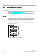
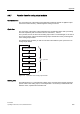
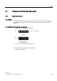
8 DI NAMUR with "8 DI NAMUR" configuration
● Assignment of the process input image (PII)
&KDQQHOVWRRILQSXWVLJQDO
9DOXHVWDWXVIRUFKDQQHOVWR
%
,QSXWVLJQDOLVYDOLG
8QDVVLJQHG
%
,QSXWVLJQDOLVLQYDOLG
6IRUPDW
(%[
(%[
(%[
Figure A-10 PII with "8 DI NAMUR" configuration
● Assignment of the process output image (POI)
The POI is not assigned.