
Operating instructions

Brief instructions on commissioning ET 200S
2.1 Commissioning on PROFIBUS DP
ET 200S
Operating Instructions, 08/2008, A5E00515771-06
27
2.1.7 Evaluating diagnostic messages
Introduction
In this example, you generate diagnostic messages by provoking errors on the ET 200S. In
the event of an error, OB 82 is started. You evaluate the start information in OB 82.
Tip: Call SFC13 in OB 82, and evaluate the diagnostic frame.
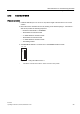
Removing and inserting the 2 DI DC24V HF digital electronic module
1. Remove the 2 DI DC24V HF electronic module from the terminal module during
operation.
2. Observe the status LEDs on the IM 151-1 STANDARD:
– SF: lights up → there is a diagnostic message.
– BF: off
– ON: lights up
Result: The ET 200S continues to run error-free.
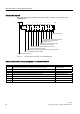
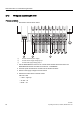
3. Evaluate the diagnostic information:
Result:
– Station status 1 (byte 0): Bit 3 is set → external diagnostics
– ID-related diagnostics: Byte 7.1 is set → slot 2
– Module status: bytes 19.2 / 19.3: 11
B
→ no module
4. Reinsert the removed electronic module into the terminal module.
Result:
– Status LED on the IM 151-1 STANDARD:
SF: off
BF: off
ON: lights up
– The diagnostic message is deleted.