
Operating instructions

Wiring and assembly
5.2 Operating the ET 200S on a grounded incoming supply
ET 200S
Operating Instructions, 08/2008, A5E00515771-06
75
5.2 Operating the ET 200S on a grounded incoming supply
Introduction
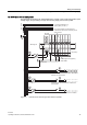
In this section, you will find information on the overall configuration of an ET 200S distributed
I/O system on a grounded incoming supply (TN-S system). The specific subjects discussed
are:
● Disconnecting devices, short-circuit and overload protection to VDE 0100 and VDE 0113
● Load voltage supplies and load circuits.
Grounded incoming supply
In grounded incoming supplies, the neutral conductor of the supply line is grounded. A single
fault between a live conductor and ground or a grounded part of the installation results in
tripping of the protective devices.
Safety isolation
Safe electrical isolation must be provided for:
● Modules that require supply with voltages ≤ 60 VDC or ≤ 25 VAC.
● 24 VDC load circuits
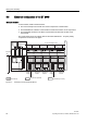
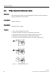
Configuring the ET 200S with ungrounded reference potential
As of IM151-1 BASIC (6ES7151-1CA00-0AB0), IM151-1 STANDARD (6ES7151-1AA02-
0AB0), IM151-1 FO STANDARD (6ES7151-1AB01-0AB0), IM151-1 HIGH FEATURE
(6ES7151-1BA00-0AB0), IM151-3 PN, IM151-3 PN HIGH FEATURE and IM151-1
COMPACT, the ground M of the nominal supply voltage of the IM151-x is connected to the
mounting rail (grounding conductor) via an RC combination, thus making a ground-free
installation is possible.
To divert interference current, the reference potential of the IM151-x is connected internally
to the mounting rail (protective conductor) via an RC combination (R = 10 MΩ / C = 22 nF).
High-frequency interference currents are thus discharged, and static charge is prevented.